Distance sensor demo device
2. Mechanical design
Parts were designed with OnShape:
Notice the different parts for each sensor. In the top part, there is a slot for standard LCD-display. 3D-printed parts are good for hiding sharp corners of the aluminium part. Hexagon-shaped holes were drawn for nuts in order to make assembly of the device easier. This resulted that only Allen wrench and screwdriver were needed for assembly.

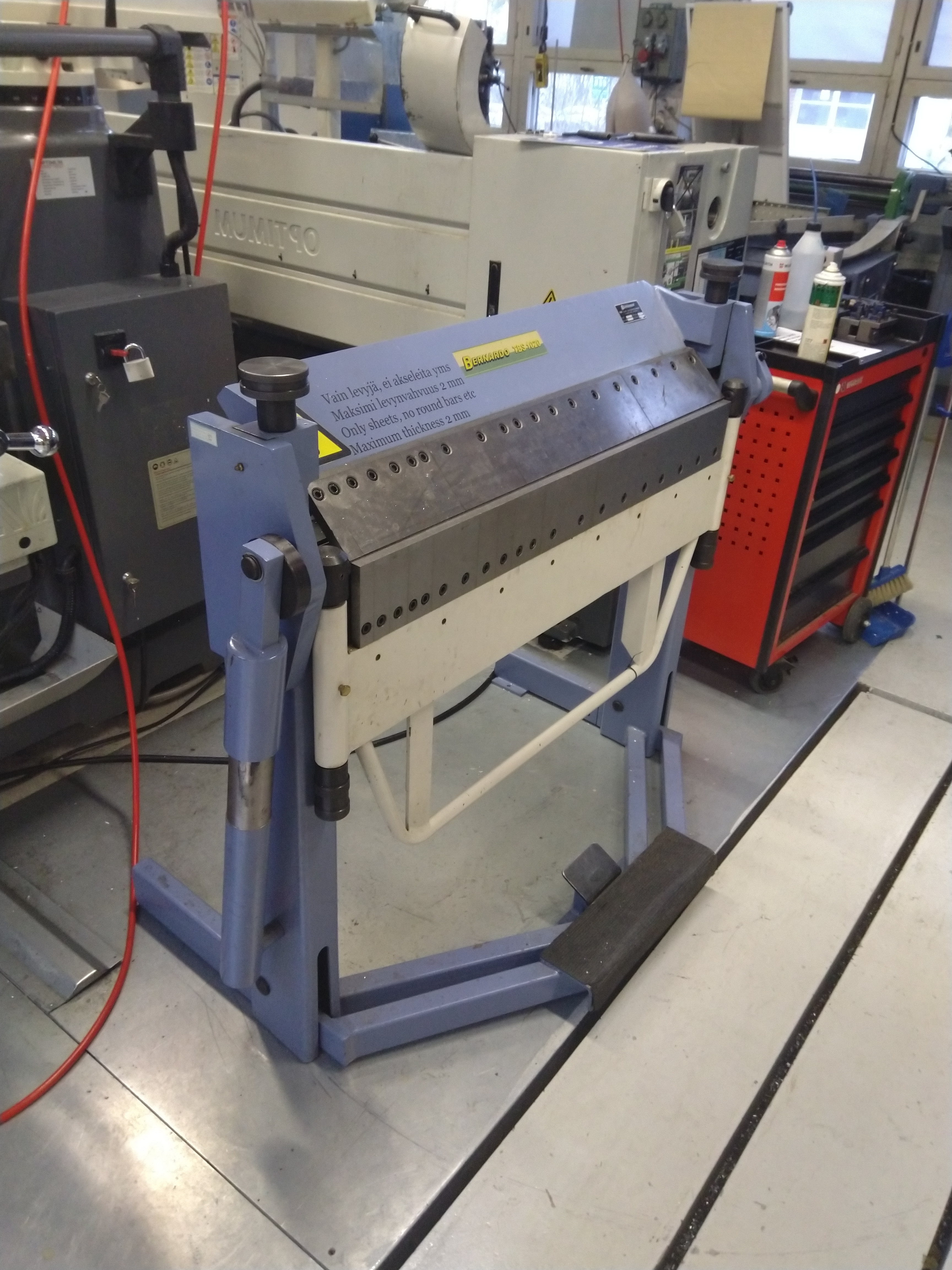
The main part of the frame was bent from aluminium. Aluminium provides rigidness and clean look, but bending with manual sheet bender (the one in the picture below) causes some unexpected features. For sheet metal parts bending is the most used way of making different shapes.


Other parts were 3d-printed. As stated above, the bent aluminium frame did cause some challenges, like the variation of curvature in the corners of the part. This had to be simulated also in the CAD-models for the prints. The faceplate was tricky to print, as it was so close to the maximum print area of Ultimaker printers.


Sensors are attached to the frame with adjustable parts with spring-loaded bolts. This was done for easier calibration but later came out that adjusting the code is enough for this accuracy level. For battery cover, a design similar to basic remote control lids was used. Making springs by 3D-printing may not be the best option for lids opened often, but with the small power consumption and infrequent need for a battery change, this should work fine.
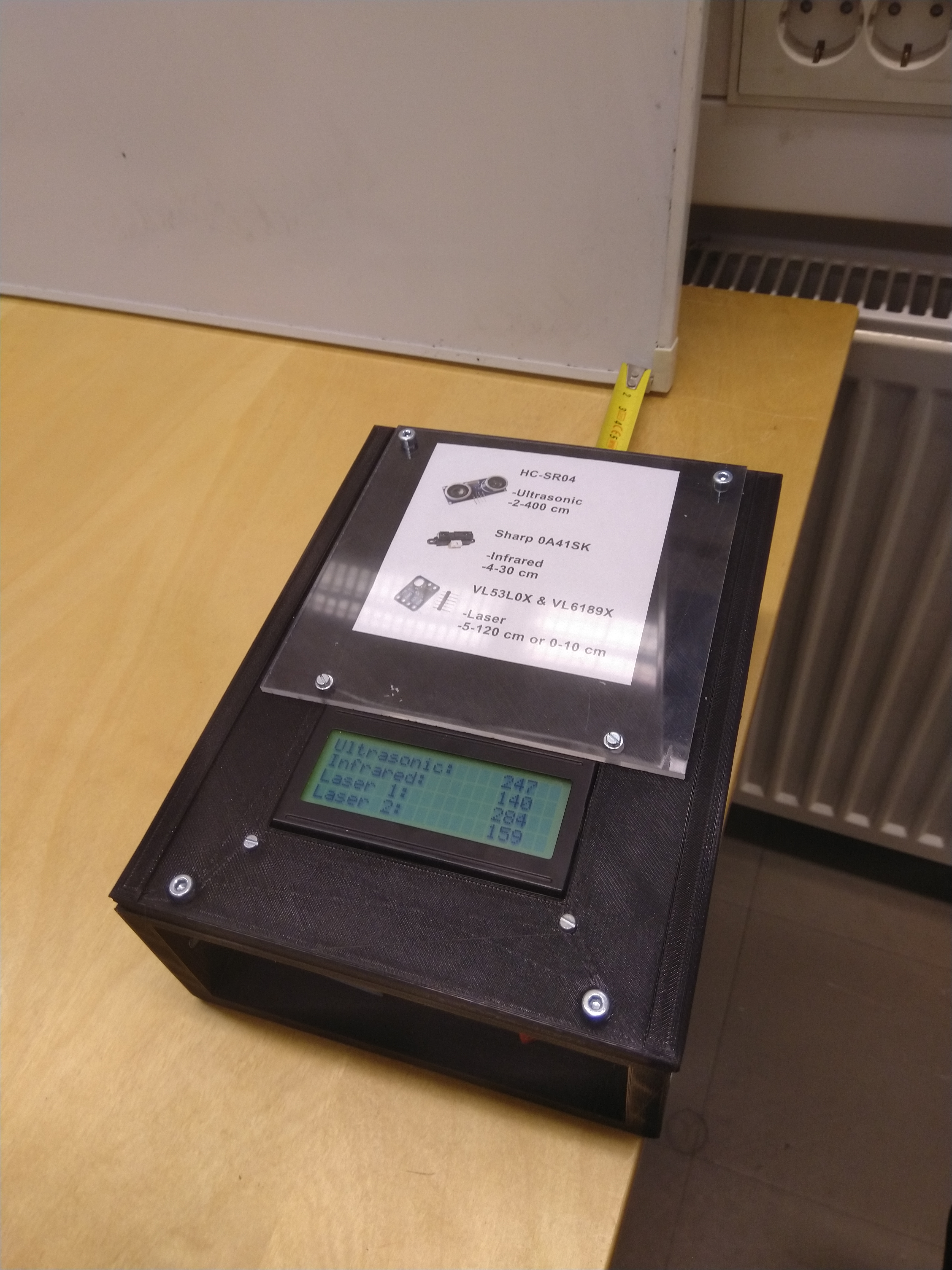
Because most of the sensors are hidden behind 3D-printed parts, pictures of the sensors were printed and added to the top part under a thin sheet of acrylic.
