H Bridge
| Site: | MyCourses |
| Course: | KON-C3003 - Mekatroniikan harjoitustyö, Luento-opetus, 10.1.2023-13.4.2023 |
| Book: | H Bridge |
| Printed by: | Guest user |
| Date: | Thursday, 3 April 2025, 10:04 PM |
Description
Device demonstrating the working principle an H bridge electrical circuit
1. About the project
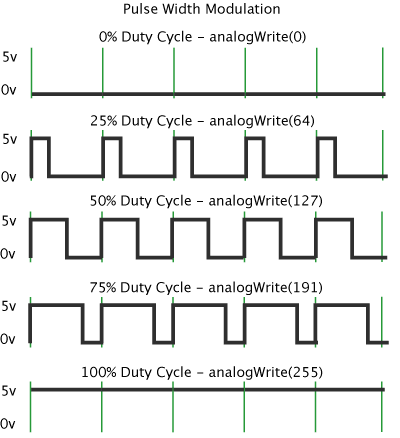
The main purpose of this device is to demonstrate the structure of an H bridge electrical circuit. This is achieved by showing both the schematics and the actual components of the structure. Because H bridge is often used to control the direction of a DC motor, the device also features a motor speed controller which is done by manipulating the duty cycle of a square wave (pulse width modulation).
2. The device
This chapter contains information about the functionality of the device.2.1. General design
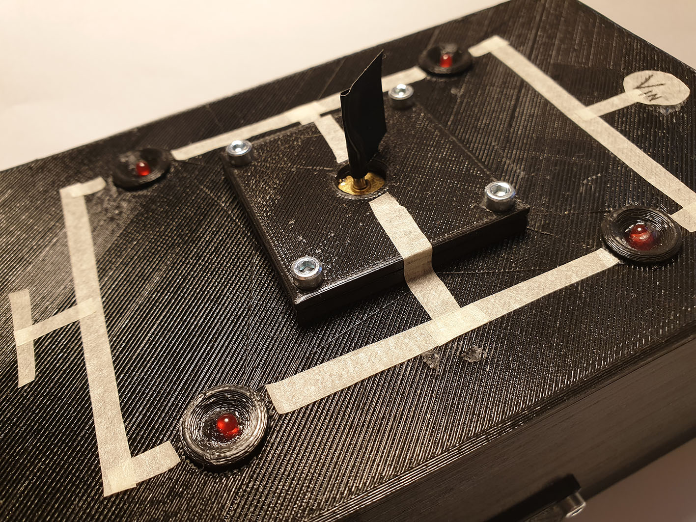
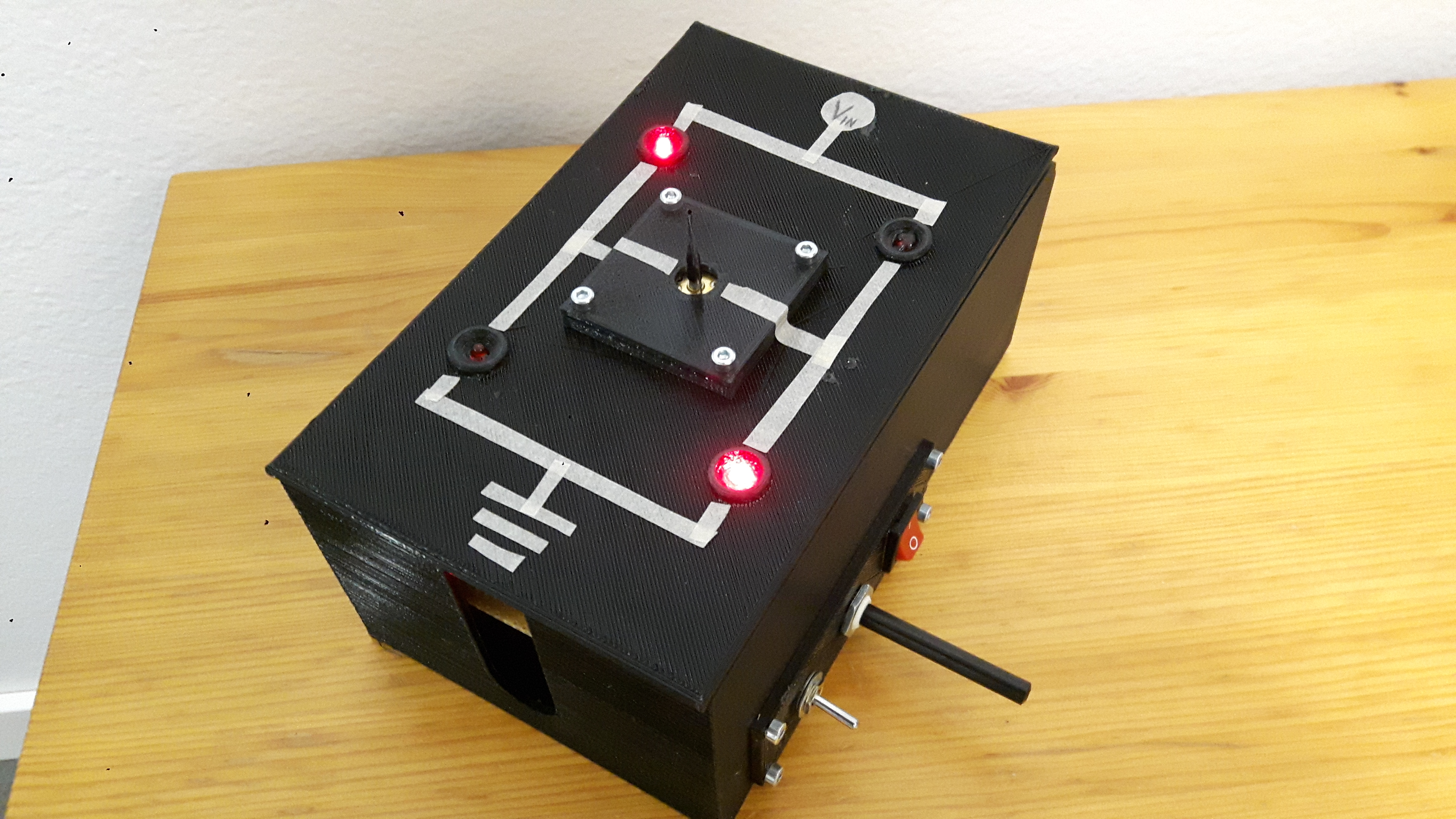
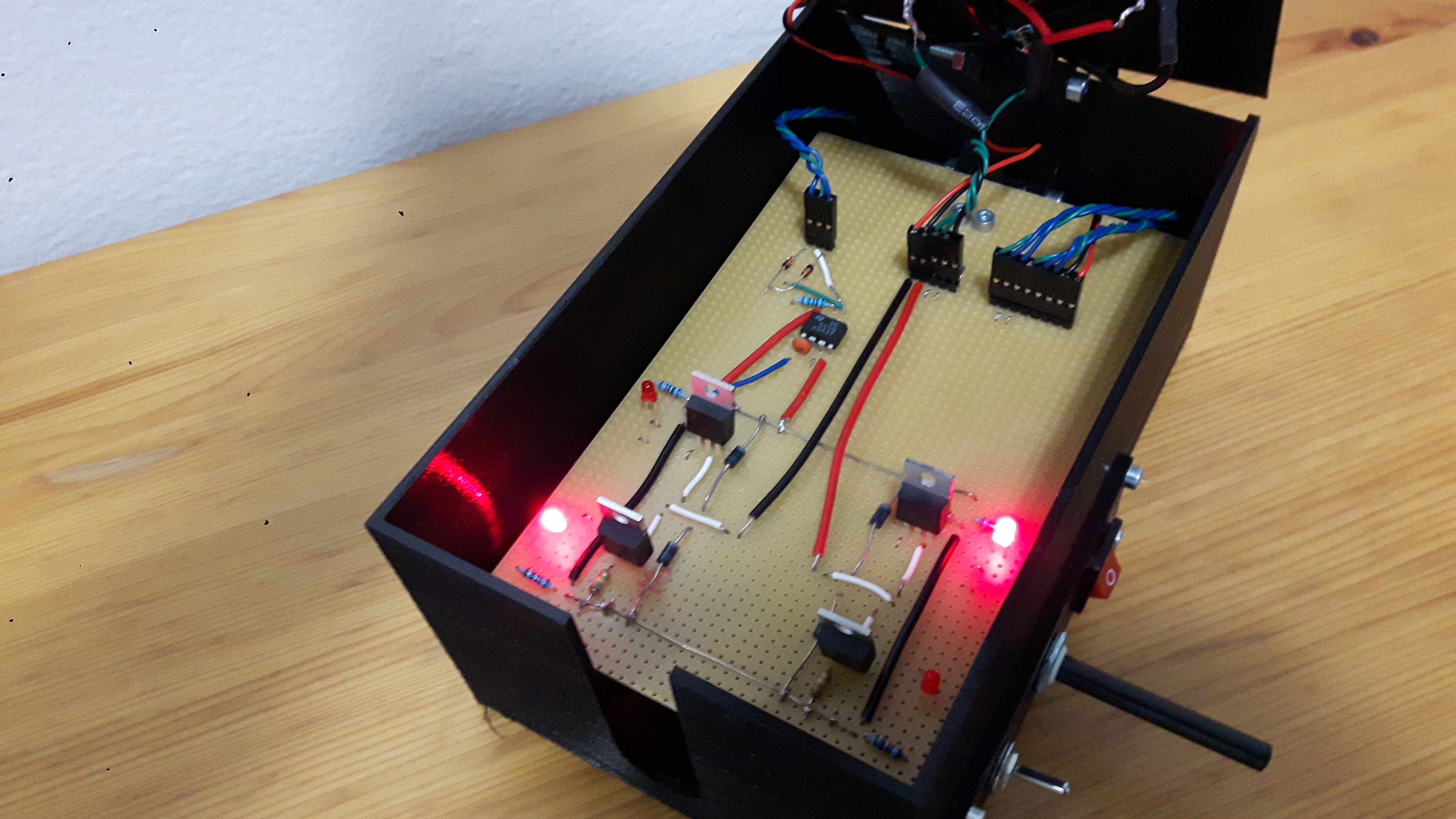
The mechanical structure of the device consists of a box that has two lids on hinges. The box and the top lid are 3D printed. The upper lid has a picture of the schematics of the H bridge as well as indicator LEDs to tell which MOSFETs are currently activated. There is also a small DC motor in the middle of the upper lid. The lower lid is a breadboard with the actual working components wired.
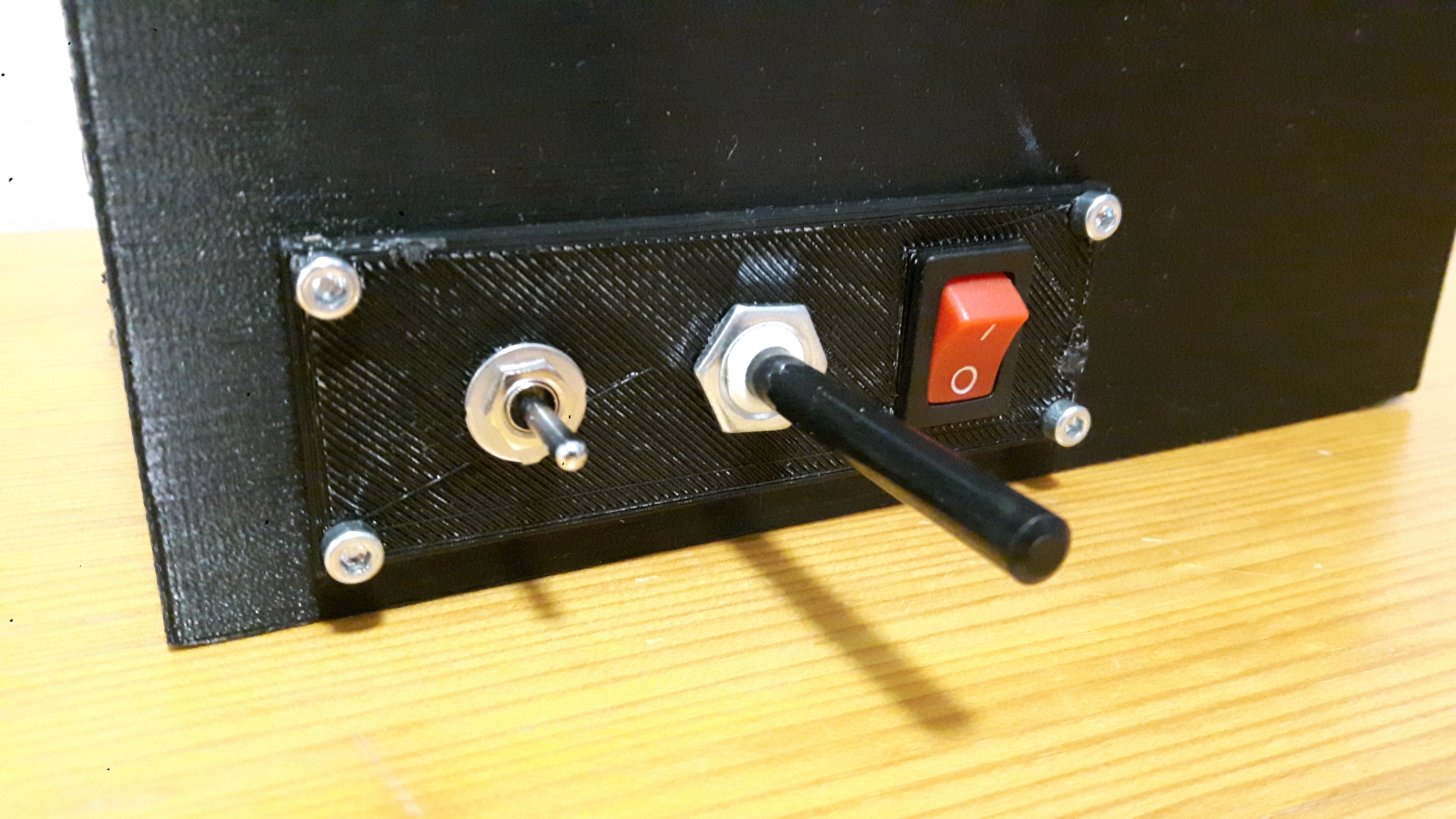
All of the wirings are done on the side of the hinges in order to avoid damage (and also for improved aesthetics). The controls of the device are placed on the side for easier and cleaner wiring. The motor and controls are fitted on a small separate 3D printed part to ensure they fit in the case a replacement part has different dimensions.The device is powered with a 9 V battery.
2.2. H bridge and indicator LEDs
The H bridge is built by using N-channel MOSFETs (FDP7030BL). The diodes in the schematic are there to protect the MOSFETs from back EMF. The actual H bridge circuit is placed on the stripboard, which acts as a lower lid.
LEDs on the upper lid are not connected to the output of the speed controller. This would interfere with the functionality of the circuit. Instead, they are operated by a 3-way switch (on-off-on), which also controls the H bridge.It is important that the current always goes through the load (DC motor). All the MOSFETs are not to be turned on simultaneously. Therefore the correct wiring on the switch is essential.
2.3. PWM motor speed control
The motor speed is controlled by a 555 timer circuit. Its output is fed to the gate of the MOSFETs. The speed of the motor is altered by modulating the pulse-width of the output. The duty cycle of the signal is controlled with a variable resistor (potentiometer).
The 555 timer IC is used in astable mode (not monostable because it generates only a single pulse).

3. Schematics
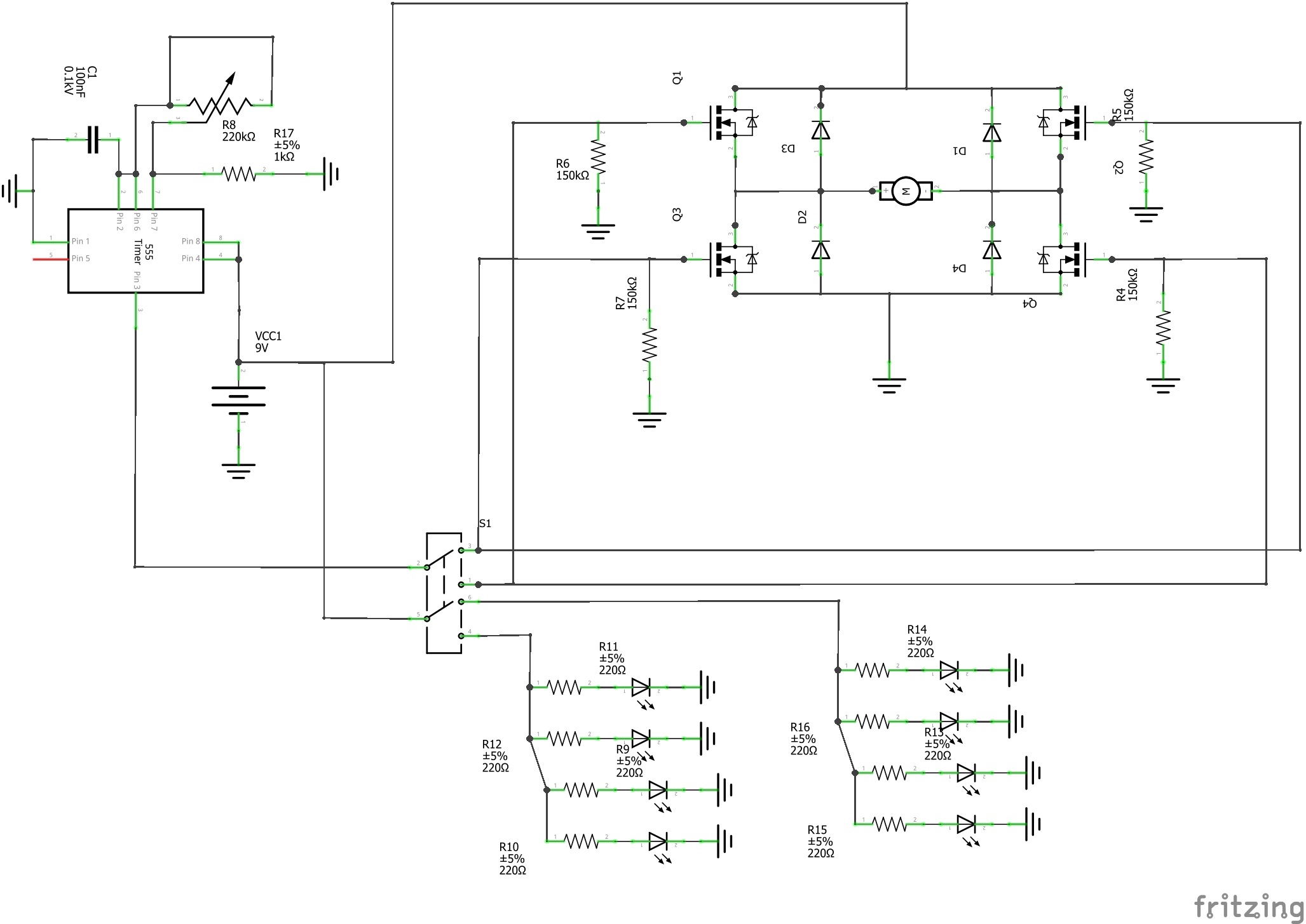
Schematics of the 555 timer IC and the H-bridge.
4. Wiring of the connectors
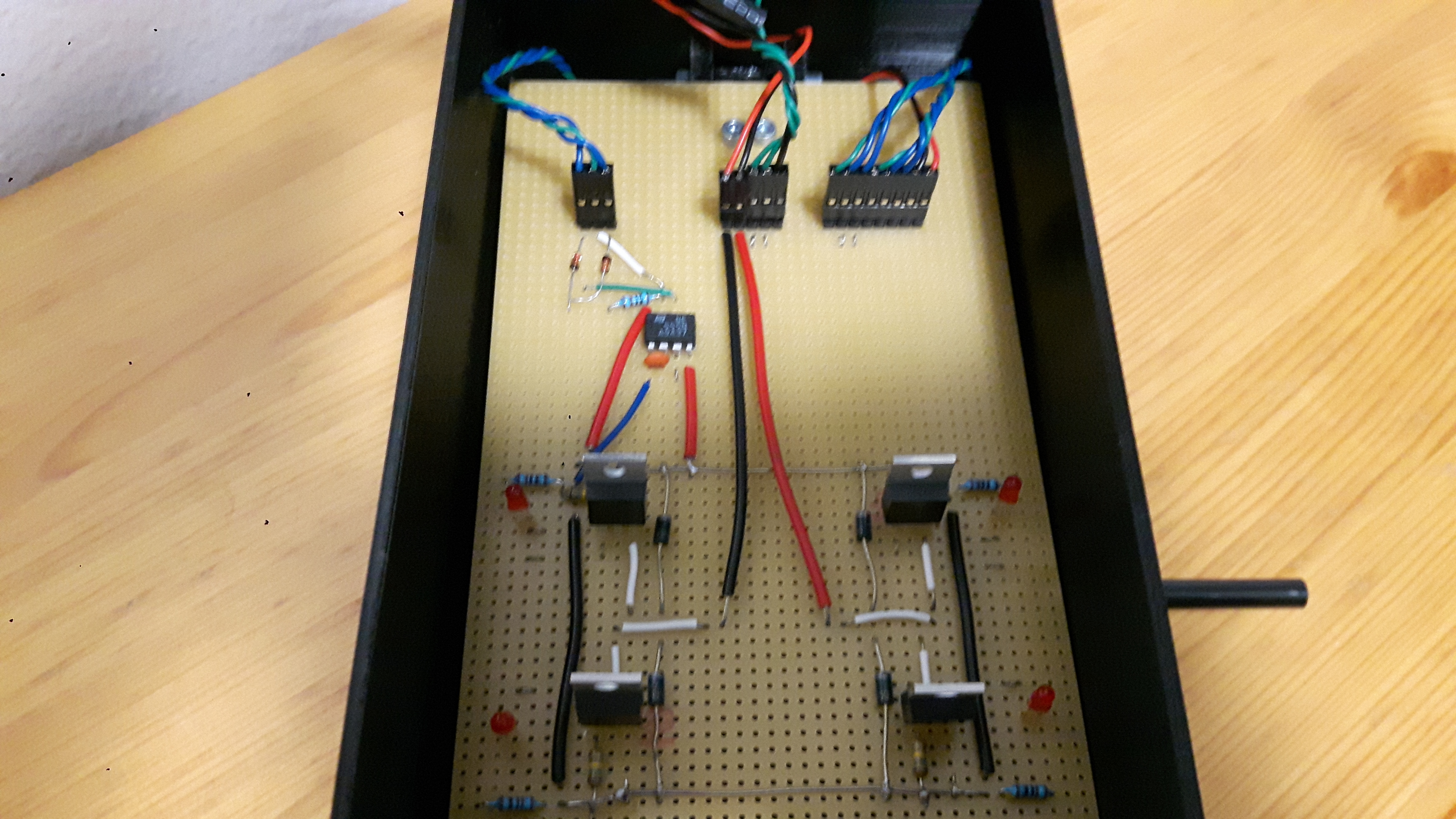
Connectors from left to right.
| Blue | Green | Blue |
|---|---|---|
| Side | Middle | Side |
The direction of this connector only determines the direction of the potentiometer.
| Red | Black | Green | Green | Black |
|---|---|---|---|---|
| Motor | Motor | LED out 1 | LED out 2 | Ground |
This connector is divided into 2 parts; the motor and LEDs. The wrong direction of motor wires doesn’t cause problems since it is a DC motor. However, the 3-wire connector must be wired correctly.
| Green | Blue | Blue | Green | Blue | Blue | Black | Red |
|---|---|---|---|---|---|---|---|
| PWM from the 555 to the switch | PWM 1 from the switch | PWM 2 from the switch | 9V to the switch | LED 1 from the switch | LED 2 from the switch | Ground from the 9V battery | 9V from the battery (through the main power switch) |
6. Parts used
| 555 timer IC | (http://www.ti.com/lit/ds/symlink/ne555.pdf) |
|---|---|
| 4x MOSFETs | (http://www.mouser.com/ds/2/149/FDP7030BL-1008136.pdf) |
| 220 Kohm linear potentiometer | (https://www.partco.fi/en/electronic-components/passives/potentiometers/basic-potentiometers/6mm_linear_potentiometers/5335-p6mlin-220k.html?search_query=220+kohm&results=28) |
| 4x diodes | (https://www.vishay.com/docs/88508/1n4933.pdf) |
| 2x diodes | (https://www.vishay.com/docs/81857/1n4148.pdf) |
| Switch | (https://www.partco.fi/en/electromechanics/switches/toggle-switches/miniature-toggle-switches/7301-kyt-ms500r.html) |
| 9V Battery enclosure | (https://www.partco.fi/en/batteries/battery-holders/2633-parpid-9v.html) |
| Motor | (https://www.partco.fi/en/electromechanics/motors/dc_motors/19505-mot-n20240.html) |
| 8x LEDs | |
| 1 nF capacitor | |
| 8x 220 ohm resistor | |
| 1 Kohm resistor | |
| 4x 150 kohm resistor | |
| Main Power switch |
7. Useful links
MOSFET as a switch
https://www.electronics-tutorials.ws/transistor/tran_7.html
555 Timer
https://www.electronics-tutorials.ws/waveforms/555_timer.html
https://howtomechatronics.com/how-it-works/electronics/555-timer-ic-working-principle-block-diagram-circuit-schematics/
PWM
https://www.arduino.cc/en/tutorial/PWM
https://www.electronics-tutorials.ws/blog/pulse-width-modulation.html
H-bridge
https://hackaday.com/2014/04/25/a-h-bridge-motor-controller-tutorial-makes-it-simple-to-understand/

