CHEM-E4185 - Electrochemical Kinetics, 25.02.2019-29.05.2019
This course space end date is set to 29.05.2019 Search Courses: CHEM-E4185
Kirja
8. Impedance technique
8.10. Similarities of the equivalent circuits
The challenge in the interpretation on the
impedance data is that the data may fit with more than one equivalent circuit.
It is therefore crucial for the researcher to know or make an educated guess
about the processes in the system. Three different circuits are presented in
Figure 8.29 that all give the same impedance plot; the values of the elements
are obviously not equal in different circuits.
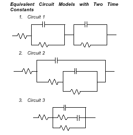
Figure 8.29. Three different equivalent circuits that give similar impedance.
The first circuit in Figure 8.29 could illustrate a membrane system. The two RC circuits would correspond to the surfaces of the membrane, and the resistor in front of the system would include all the ohmic resistance of the system. The second circuit is typical for an electrode, when the electrode reaction is accompanied by an adsorption step (see chapter 8.3.2 and Figure 8.15). The third circuit includes a series combination of a resistor and a capacitor, illustrating, for example, dipolar relaxation in the solid phase [1]. This circuit is therefore typical in the electrochemistry of the solid phase.
An alternative to the Randles circuit is shown in Figure 8.30.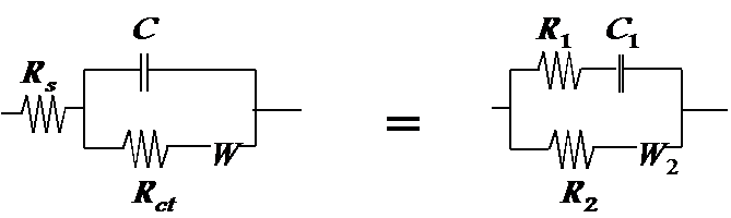
Figure 8.30. The circuit (right), which gives an identical impedance compared to the Randles circuit (left).
In corrosion research in particular it is necessary to be careful, because, as shown in Section 8.3.4, the elements may even have negative values. The loop below the real axis in Figure 8.21 can also be modeled using the parallel combination of a resistor and a negative capacitor.
[1] See, for example, J.R. Macdonald, Impedance Spectroscopy, John Wiley & Sons, New York 1987, s. 49.