CHEM-E4185 - Electrochemical Kinetics, 25.02.2019-29.05.2019
This course space end date is set to 29.05.2019 Search Courses: CHEM-E4185
Kirja
8. Impedance technique
8.1. Basic elements of impedance
A resistor R (electric resistance) is always present in an electrochemical system. Ohm’s law states that if the voltage across a resistor is E, the current through the resistor is E/R. The impedance of the resistor is therefore R.
An electrochemical reaction always takes place at the phase boundary, i.e. on the surface of an electrode or catalytic particle in a membrane. At the phase boundary, the electroneutrality condition is not complied with, but the phase boundary has an ability to store electric charge, i.e. it acts as a capacitor. The voltage across a phase boundary gives rise not only to charge transfer, i.e. current I = E/R, but also to the reorganization of charges at the phase boundary. This capacitive current can be expressed as
| \( \displaystyle I_C=C_{dl}\frac{dE}{dt}=j\omega C_{dl}E \) | (8.6) |
|---|
Capacitive impedance is obtained using simple algebra:
| \( \displaystyle Z_C=\frac{1}{j\omega C} \) | (8.7) |
|---|
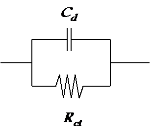
Since total current across the phase boundary, IT, is IT = E/R + jwCE = (1/R + jwC)E, the admittance of the phase boundary is Y = 1/R + jwCdl and the impedance Z = Y-1. Parallel combination of the charge transfer resistance Rct and double layer capacitance Cdl is therefore the simplest model of an electrode or some other phase boundary as shown in Figure 8.4.
Models of phenomena in dissolving processes, i.e. corrosion, may include also inductors. In this case, the relationship between voltage and current is expressed as:
| \( \displaystyle i=\frac{1}{L} \int Edt=\frac{1}{j\omega L} E \Rightarrow Z_L =j\omega L \) | (8.8) |
|---|
This gives us useful hints on how to determine the total impedance of a multicomponent system. The rule is to sum up the impedances of the components in series and the admittances of the components in parallel as shown in Figure 8.5.
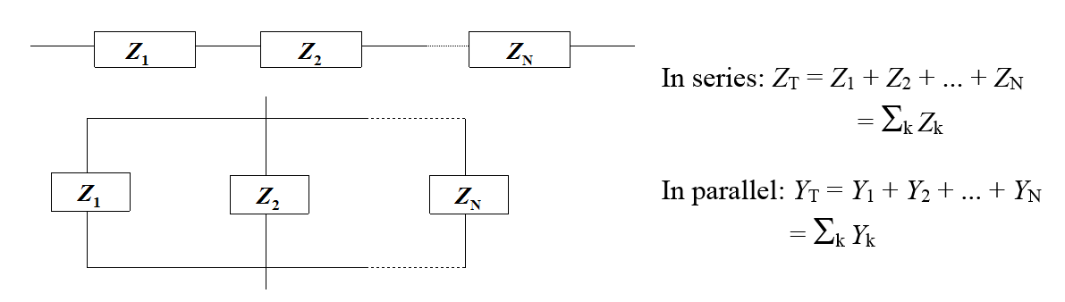
Figure 8.5. Calculation of a total impedance from component impedances.
As the impedance of a resistor is real and that of a capacitor is imaginary, any given impedance can be expressed in terms of a resistor and capacitor in parallel:
| \( \displaystyle Z=R_p+1/j\omega C_p=R_p-j/\omega C_p \) | (8.9) |
|---|
In Equation (8.9), Rp and Cp
are so-called pseudo resistance and capacitance. They are of course functions
of frequency, which explains the use of the prefix ’pseudo’. Sometimes the
imaginary part of an impedance is called reactance. The classical impedance
measurement technique is based on an application of Equation (8.9). In this
method, a very precise impedance bridge is used as shown in Figure 9.6.
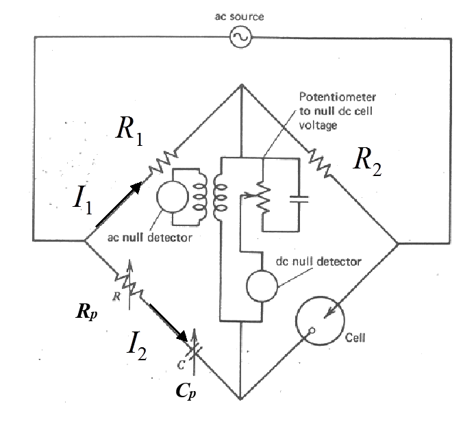
In the middle of the bridge, there are null detectors for both DC and AC. The idea of the measurement is to adjust the values of Rp and Cp so no current is detected at the null detectors between the upper and lower arm of the bridge. When the bridge is at equilibrium, the upper and lower arms are at the same potential and Kirchoff’s second rule can be used to write the equilibrium condition as
\( \begin{cases}I_1R_1=I_2(R_p-j/\omega C_p)\\I_1R_2=I_2Z\end{cases} \)
where R1
and R2 are known resistors
and Z the impedance of the cell studied. Dividing both sides of the equations, impedance Z is obtained:
| \( \displaystyle\frac{R_1}{R_2}=\frac{R_p-j/\omega C_p}{Z} \) | (8.10) |
|---|
Setting R1 = R2 results in Equation (8.9).
The series combination of an inductor and the capacitance brings about an interesting effect: resonance. The total impedance is a sum
| \( \displaystyle Z=j\omega L+(j\omega C)^{-1}=j(\omega L-1/\omega C)=j\frac{\omega^2LC-1}{\omega C} \) | (8.11) |
|---|
Thus, if frequency \( \omega=(LC)^{-1/2} \), impedance is explicitly lost, i.e. the circuit is in resonance. This phenomenon is used for example in radio detectors or quartz crystal microbalances. The circuit includes also a resistor to restrict the current.
|
The basis
of a quartz crystal microbalance relies on the resonance phenomenon. A voltage
of a couple of volts is set across a thin quartz crystal, whereupon the crystal
starts to vibrate due to the piezoelectric effect, i.e. the planes in the
crystal structure start to move with respect to one another. Typical crystals
used in microbalances oscillate at 5 or 10 MHz resonant frequency. When a small
mass is deposited on the crystal, the oscillation frequency becomes smaller
according to Sauerbrey equation:
where \( \Delta f \) is the change in frequency (Hz), f0 is the resonant frequency of a clean crystal, N = 166.8 kHz cm, \( \rho_q \) density of quartz, 2.648 g cm-3, ja \( \Delta m \) mass deposited on the crystal. E.g. Adding a mass of 10 ng cm-2 to a 10 MHz crystal, for example, changes frequency 2.26 Hz. The most sensitive microbalances can easily resolve an added mass of 1 ng cm-2. Both changes in mass and the viscoelastic
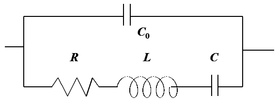
properties of a film can be measured using QCM. The analysis is based on the
admittance analysis using a Butterworth-van Dyke circuit, which describes the
oscillation of the crystal.
In the circuit, C0
is the capacitance of the crystal and the lower arm describes the
resonant phenomenon; the admittance of the lower arm has a sharp peak at the
resonance frequency. The values of R, L, and C can be related to the density
and viscosity of the layer based on a very complex theory [1].
The layer must be at
least 100 \( \mu \)m in thickness for the viscoelastic behavior to be able to be observed. If the crystal is in solution, the density
and viscosity of the solution have a similar effect on the crystal as a viscous
layer on the surface. The change in admittance when the crystal is submerged in
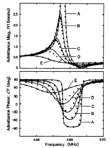
aqueous solutions of glycerol with varying concentrations is shown in Figure 9.8.
Figure 8.8. Admittance and phase angle of a quartz crystal as a function of environment,
and density-viscosity product of contacting fluid \( \rho\eta \) (g2 cm-4 s-1). A: air, \( \rho\eta \) = 2\( \times \)10-7; B: water, \( \rho\eta \) = 0.010; C:
43 % glycerol, \( \rho\eta \) =
0.044; D: 64 % glycerol, \( \rho\eta \) = 0,15; E: 80
% glycerol, \( \rho\eta \) =
0.72. Source: see footnote. The dissipation factor D, or ratio of dissipation energy Ediss of the mechanical energy stored in the film, Estored is easy to determine using the values of circuit components in the model:
The quartz crystal is frequently coated with gold to allow for its use as an electrode. Combining mass data with electrochemical data makes it possible to distinguish between the responses of an electroactive and neutral species, which is important in research of conducting polymers. The method is called an electrochemical quartz crystal microbalance (EQCM). |
|---|
[1] S.J. Martin, V.E. Granstaff, G.C. Frye, “Characterization of a Quartz Crystal Microbalance with Simultaneous Mass and Liquid Loading”, Anal.Chem. 63 (1991) 2272.