
OT14 Waterjet Cutting K006a
Preparing files for the waterjet
- Please
use a CAD program for the drawing. In the file, have only lines, that will be
cut. For example, Rhinoceros 3D, SolidWorks or Illustrator works fine for designing your parts.
- Take the thickness of the cutting jet, ~1mm, into consideration.
- Line type and width don't matter.
- Have the lines on only one plane and layer.
- The gap between cut items can be 2mm.
-
Export
into a metric dxf file or use the native format from CAD.
From a 2d drawing, simple tilted operations can be machined. Ie. beveled cut or a cut at a certain angle. If your cutting involves more complex geometries or many angled cuts, please send a 3d model.
- The model should be the same thickness as the material being cut
- The maximum angle is 59°
-
Export into
metric step file
Small pieces (smaller than your palm), need to be held onto the base material. A simple tab can be created when making the cutting paths at the waterjet, but if you are cutting several items please hold the pieces together with small connecting bridges between the pieces or create a comb connecting the pieces. This way you will be in control of where the connections are and can be sure they will intervene with your design.
When cutting fragile materials please provide more room between each item. For glass 10mm
Workholding for sheet materials takes roughly 50mm around the cutting area of the file.
Making files with Rhino3d
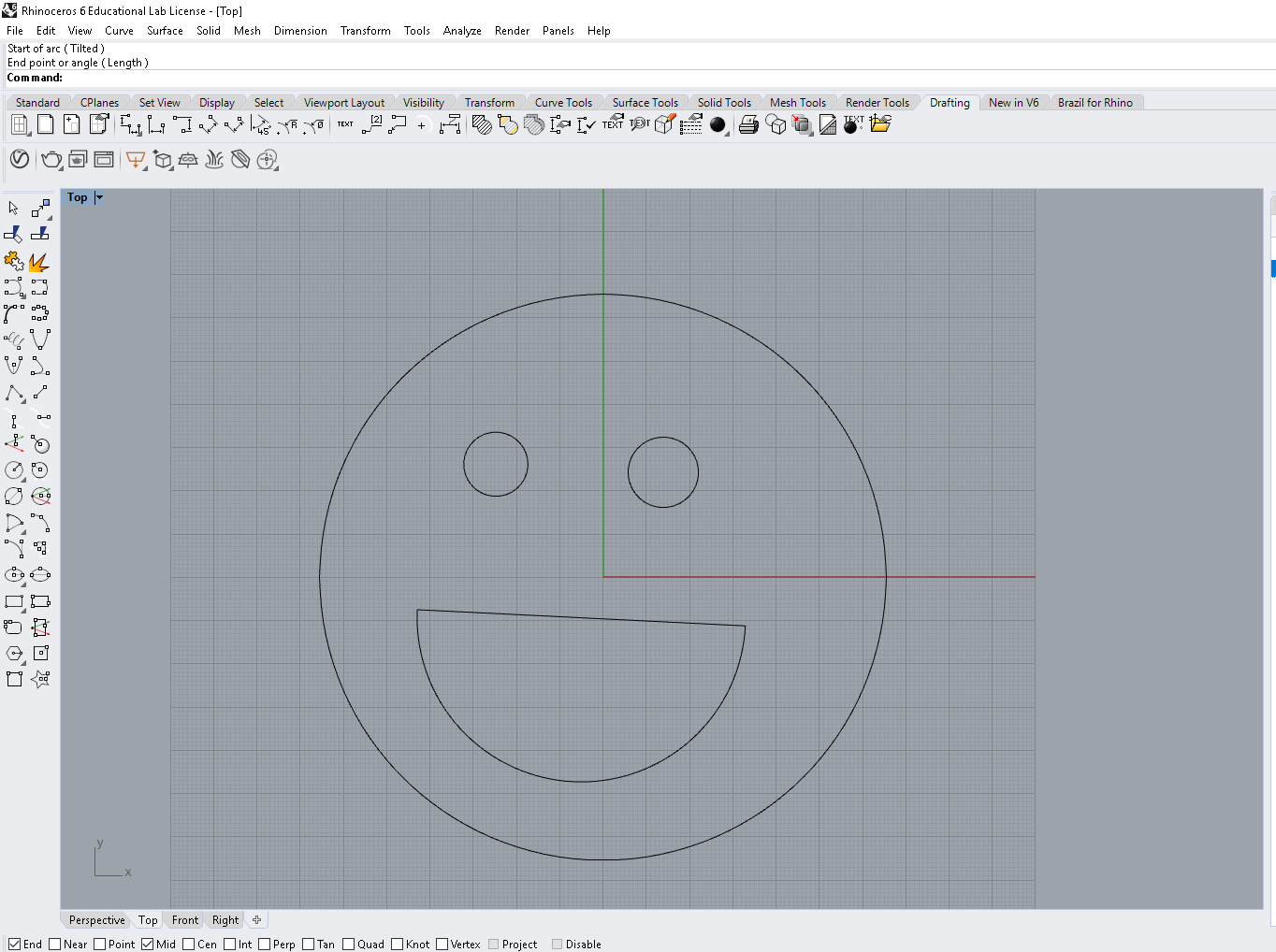
Kuva: Rhino3d
Draw cut geometries on one level. Have only cut geometries on the drawing.
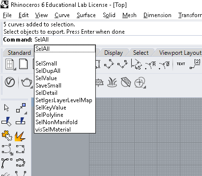
Kuva: SelAll
Command SelAll selects all
SelDup selects duplicate lines which can be deleted.

Kuva: Export
Export command lets you save your drawings
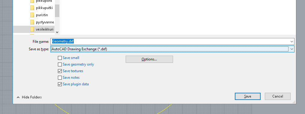
Kuva: Tallenna DXF
Save as dxf.
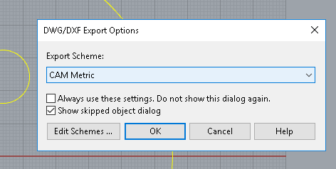
Kuva: tallenna CAM metric
Choose CAM Metric from dxf export options
For advanced use, the layers can be used to determine cutting quality.
| 1 | quality 1 cut |
|---|---|
| 2 | quality 2 cut |
| 3 | quality 3 cut |
| 4 | quality 4 cut |
| 5 | quality 5 cut |
| 6 | etch |
| 7 | Scribe |
| 8 | water only |
| 21 | quality 1 slit |
| 23 | quality 3 slit |