CS-C3150 - Software Engineering, Lecture, 2.9.2024-29.11.2024
Topic outline
-
This module covers software modeling and implementation, and consists of one lecture, two chapters in the book, one quiz and one written assignment.
-
This module has of one compulsory and nine recommended videos.
- Module introduction and overview by Casper Lassenius (40 min)
Recommended (highly recommended in bold font) videos - Derek Banas UML 2.0 Tutorial
- UML 2.0 Tutorial - Use Case Diagrams (13 min)
- UML 2.0 Activity Diagrams (12 min)
- UML 2.0 Class Diagrams (17 min)
- UML 2.0 Sequence Diagrams (12 min)
- UML 2.0 Communication Diagrams (10 min)
- UML 2.0 Timing Diagrams (9 min)
- UML 2.0 Component Diagrams (18 min)
- UML 2.0 State Machine Diagrams (13 min)
- UML 2.0 Deployment Diagrams (8 min)
-
Reading 1: Software Design File PDFExcerpt from: Sommerville, I. (2016) Software engineering. Tenth edition. Boston, USA: Pearson.
-
Reading 2: UML@Classroom File PDF
Supporting material for the written exercise. Use it to support your work in doing the exercises, and read-only as much as required. Tip: use it as a reference manual.
Seidl, M. et al. (2015) UML@Classroom: an introduction to object-oriented modeling. New York, NY: Springer. -
Module 7 quiz
Quiz on Software modeling and implementation
Do not take this quiz until you have studied the readings AND listened to the lecture.
The quiz is timed, and you have 30 minutes to do it.
You are allowed two attempts. You will get the grade of your best attempt. You will be shown the correct answers to the questions only after the quiz is closed.
-
Assignment: Software Modeling
In this exercise, you will both read and create software design diagrams. Use Reading 2: UML@Classroom and the linked videos explaining the various diagram types to aid your work.
This assignment contains four subtasks. Use the lecture videos, as well as Reading 2: UML@Classroom to help you.
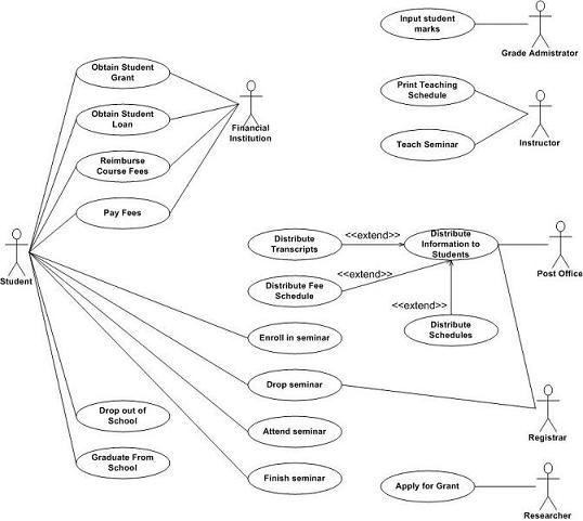
1. Explain the following use-case diagram.

2. Class diagram
Model a simplified email system using a UML class diagram. The system consists of several core components that interact with one another. Your class diagram must represent these components, their relationships, and relevant details such as attributes and methods.
Components to Model:
- User
- Users interact with the email system.
- Each user has a unique username and email address.
- Users can send and receive emails.
- Methods: sendEmail(), receiveEmail()
- Email
- Represents an email message.
- Each email has a sender, recipient(s), a subject, and a body.
- Emails can have attachments.
- Methods: addAttachment(), removeAttachment(), send()
- Attachment
- Represents an attachment to an email.
- Each attachment has a filename and a file size.
- An email can have zero or more attachments.
- Methods: download(), getSize()
- Inbox
- Each user has an inbox to store received emails.
- An inbox can contain multiple emails.
- Methods: addEmail(), removeEmail()
Requirements:
- Generalization:
- Model a generalization relationship between User and a possible subclass, AdminUser, which has additional methods to manage system users (e.g., addUser(), removeUser()).
- Relationships & Multiplicities:
- Each User can have one Inbox, but each Inbox can have many emails.
- Each Email must have one sender (a User), and one or more recipients (Users).
- Represent relationships using appropriate multiplicities.
- Attributes:
- Each class should include at least two attributes that represent important characteristics (e.g., username in User, subject in Email, filename in Attachment).
- Methods:
- Include methods for each class that describe its basic functionality (e.g., sendEmail() for User, download() for Attachment).
In addition to drawing the diagram, please also provide a brief description explaining the key relationships and design choices you made.
3. Sequence diagram
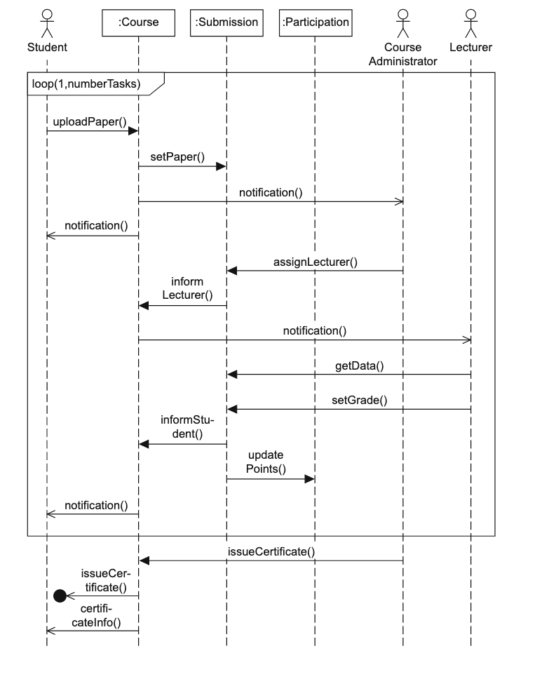
Explain the following sequence diagram:

4. State chart
Draw a UML state-chart diagram that models the behavior of a coffee machine. The machine allows users to select different types of coffee, brews the coffee, and dispenses it. Your diagram should show the various states of the coffee machine and how it transitions between those states.
Coffee Machine Behavior:
The coffee machine can transition between several states during its operation. Below is a description of the states and selections to include:
- Idle State
- The machine starts in the idle state, waiting for a user to make a coffee selection.
- It will transition out of this state when a user selects a coffee type.
- Coffee Selection State
- The user selects one of the available coffee types: Espresso, Cappuccino, or Latte
- After the selection is made, the machine verifies that there are sufficient ingredients to make the coffee.
- If the selection is valid and ingredients are available, it transitions to the brewing state. If not, it transitions to the error state.
- Brewing State (Compound State)
- After a valid selection, the machine enters the brewing state. This state consists of two concurrent actions:
- Water Heating: The machine heats the water.
- Bean Grinding: The machine grinds the coffee beans.
- Both actions must complete before brewing is finished.
- The brewing process can vary slightly depending on the coffee type selected (e.g., more milk for Latte or foam for Cappuccino).
- Dispensing State
- After brewing, the machine dispenses the selected coffee (Espresso, Cappuccino, or Latte) to the user.
- Once dispensing is complete, the machine returns to the idle state.
- Error State
- If there is an issue during selection (e.g., not enough ingredients or invalid selection), the machine enters the error state.
- After the issue is resolved, the machine returns to the idle state.
Requirements:
- States:
- Identify and model the different states of the coffee machine (e.g., idle, coffee selection, brewing, dispensing, error).
- Initial State:
- The diagram should start with an initial state leading to the idle state.
- Coffee Selection:
- Explicitly model the coffee selection state where the user chooses from Espresso, Cappuccino, or Latte.
- Compound State:
- Model the brewing process as a compound state with two concurrent activities: water heating and bean grinding.
- Concurrent States:
- Represent water heating and bean grinding as concurrent states during the brewing process.
- Transitions:
- Model the transitions between states, including events or triggers that cause state changes (e.g., selection made, brewing completed, error encountered).
In addition to the diagram, please provide a short explanation describing your diagram, focusing on the coffee selection, compound, and concurrent states.
- User
-
