KON-C3003 - Mekatroniikan harjoitustyö, Luento-opetus, 11.1.2022-14.4.2022
This course space end date is set to 14.04.2022 Search Courses: KON-C3003
Pre-assignment 1
Topics: | Pre-lab task: |
Voluntary task: | Videos: |
|---|---|---|---|
| - Introduction to Arduino - Digital & Analog IO - Polling and interrupts |
- Install Arduino IDE and get familiar with it Jump to the task |
- Tinkercad simulation Jump to task | - Digital & Analog signals - PWM - Breadboard - Bands of a Resistor - LEDs & Resistors - Pull-up and pull-down resistors Go to videos (redirects to page) |
Introduction to Arduino
Arduino is a completely open-source electronics platform. Arduino boards are able to read inputs (button presses, temperature sensors, etc.) and turn them into outputs (activating a motor, blink a LED, etc.). This is done by writing instructions in the Arduino programming language and uploading them to the microcontroller on the board, which can be e.g. an Atmega328P chip. The circuitry and connectors on the Arduino boards makes it easy to program the microcontroller and connect it to an external circuit. Arduino boards are used in millions of projects and they are very popular among both beginners and professionals.
Why Arduino is popular
-
Inexpensive
-
Cross-platform
-
A simple, clear programming environment
-
Both open-source and extensible software and hardware
Arduinos official website: https://www.arduino.cc/
Digital IO
The digital pins are numbered 0 to 13.
How it works & what it's used for
Digital pins allow receiving and sending binary signals (LOW, 0V and HIGH, 5V). The pins 0 and 1 can't be used when the Arduino board is connected to a computer via USB.
Digital pins are used for actuators and sensors that operate with digital signals, e.g. motor control signals.
PWM
What pins
Digital pins marked with a tilde ~ are PWM pins.
How it works & what it's used for
Pulse Width Modulation (PWM) allows digital pins to simulate analog signals. This is achieved by quickly switching between 0 and 5V to create a square wave. The value of the simulated voltage depends on the relation between the time spent in the HIGH and LOW states, which is presented in the picture to the right.
PWM pins are used in applications where a variable signal is needed, e.g. changing the brightness of a LED.
Analog IO
What pins
The analog pins are numbered A0 to A5.
How it works & what it's used for
Arduino boards contain an analog-to-digital converter (ADC) that converts an incoming voltage level to an integer. Arduino Uno’s ADC has a 10-bit resolution which converts voltages ranging from 0-5V to integers in the range 0-1023. For example, an incoming 3V signal would be represented as 613.
Analog pins are used to read incoming signals which need a higher resolution than just a binary ON or OFF, e.g. analog sensors. However, analog pins can also be used as digital pins if needed.
Code structure
At a basic level, Arduino code is made up of three parts:To read more about coding basics such as variables and data types, read the Arduino Coding Basics document.
If you are
interested in the most common functions, read the Basic Functions document.
Monitoring a pin's state
Polling
How it works & what it's used for
Polling means to regularly check whether an input pin is receiving a desired digital signal. If the pin has the desired state, execute a piece of code, otherwise, keep doing other tasks and poll with regular intervals.
In week 1's exercises polling will be used to check if a button is being pressed. Polling is not as responsive as using interrupts, because the poll has to happen while the button is being pressed. Otherwise, it will go unnoticed.
Interrupts
How it works & what it's used for
If your application is time-sensitive and the received signals are frequent, using interrupts can give better results than polling. When an interrupt (pin) is triggered, current tasks are postponed and a specified interrupt function is executed. After the function is executed the microcontroller returns to the line in the code where it got interrupted.
In week 1 exercises interrupts will be used to react to a button press.
Basic Circuit Components

Resistors
Different components can handle different amounts of current. For example, a standard LED will burn if it is connected directly to a digital pin set to HIGH. To prevent this, a resistor of fitting size has to be connected in series with the component in question. To figure out the resistance of a resistor, you can use a table like the one to the left. There are also multiple resistor calculators online.
Breadboard
When working with an Arduino you will most likely want to use a breadboard to make it easier to connect components together, at least in the prototyping stage. Do note that connections via a breadboard are not always reliable. For a longer-lasting solution, it is recommended to solder your wires directly to a PCB.
On a breadboard, all connectors on the power lines (marked with + and -) are connected together horizontally, so e.g. connecting a power source and an actuator on the same line would connect the actuator directly to the power source.
On the other hand, the connection lines are connected vertically, so every device on the same line will receive the same signal.
Pre-lab task
Install the Arduino IDE and get familiar with its features by reading the document "Arduino Programming Environments".If you are new to Arduino, we recommend you read through the Coding basics (pages 1-3 & 5) and Basic Functions (pages 1 & 3) documents for a quick introduction to coding in the Arduino language.
Voluntary task
If you would like to get a head-start on the exercise topics, feel free to do this additional task using the circuit simulator on Tinkercad.com.Tinkercad's simulator is excellent for getting to know electronics and microcontroller programming. It contains the most common components used when making Arduino circuits, and it lets you run code on a simulated Arduino Uno.
Your task is to design a circuit where an LED turns off while a button is pressed. The LED should turn back on when the button is released.
Getting started:
1. Go to https://www.tinkercad.com and make an Autodesk account- The account is completely free and will give you access to all Autodesk products. This also includes Eagle (PCB design) and Fusion 360 (Modelling software)
2. Go to Circuits and create new Circuit
- This can be found on the front page, on the left after logging in.
3. From components add Arduino Uno R3
- Add components by opening the component view from the right top corner, and dragging and dropping components to the workspace.
4. After adding an Arduino you can enter the code editor.
- Initially, the code editor is in block programming mode. It is recommended that you switch to the text-based programming mode because it is used in the Arduino IDE when programming a physical Arduino. You can switch mode from the "Blocks" drop-down menu.
Tips:

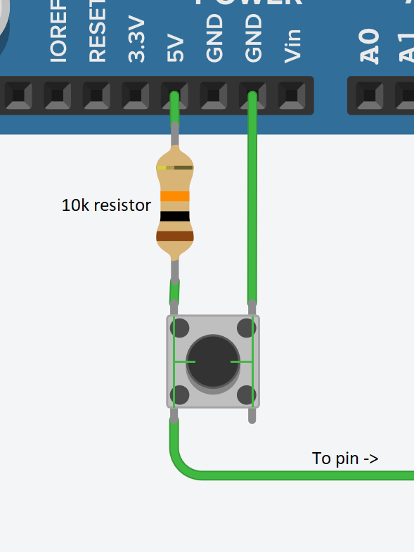
 Pull-up and pull-down resistors
This wiring ensures that a pin is not left floating. Floating means that the pin is not connected to any known voltage, which causes it to have erratic values.
If you wish the pin to be HIGH when the button is not pressed, connect it to the 5V rail. In case you want it to be LOW, connect it to GND instead.
When the button is pressed, the 5V and ground will be directly connected, and therefore a current limiting resistor of over 10kΩ is needed to prevent a short circuit.
More in-depth info about pull-up resistors can be read on Sparkfun's tutorial.
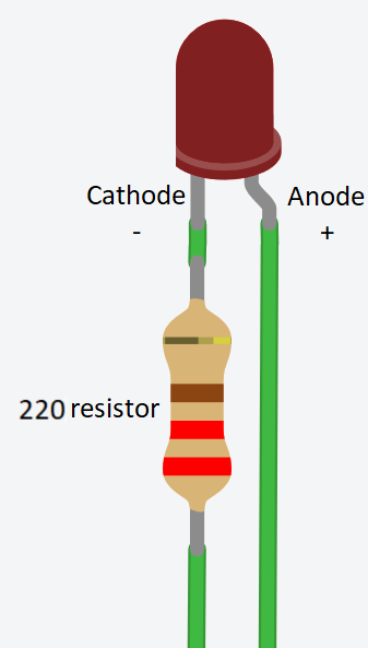
LED current limiting resistor:
A basic LED can only handle around 20mA of current. Connecting the LED directly to 5V will break it and therefore, a current limiting resistor of about 230Ω is needed. A larger resistance makes the LED dimmer, and a smaller makes it brighter.
Recommended reading:
A collection of the functions used in this task can be found in the Basic Functions document.
Click "Show solution" to reveal a complete circuit and related code.
Explanation
When the button is released, pin 2 is connected to GND, which is read as 0 (=LOW). This can be written directly to pin 13 to turn the LED off. When the button is held down, the pull-down resistor causes most of the current from 5V to go to pin 2, which will then read HIGH and subsequently turn on the LED.
