KON-C3003 - Mekatroniikan harjoitustyö, Luento-opetus, 10.1.2023-13.4.2023
This course space end date is set to 13.04.2023 Search Courses: KON-C3003
Linear actuator

4. Building instructions
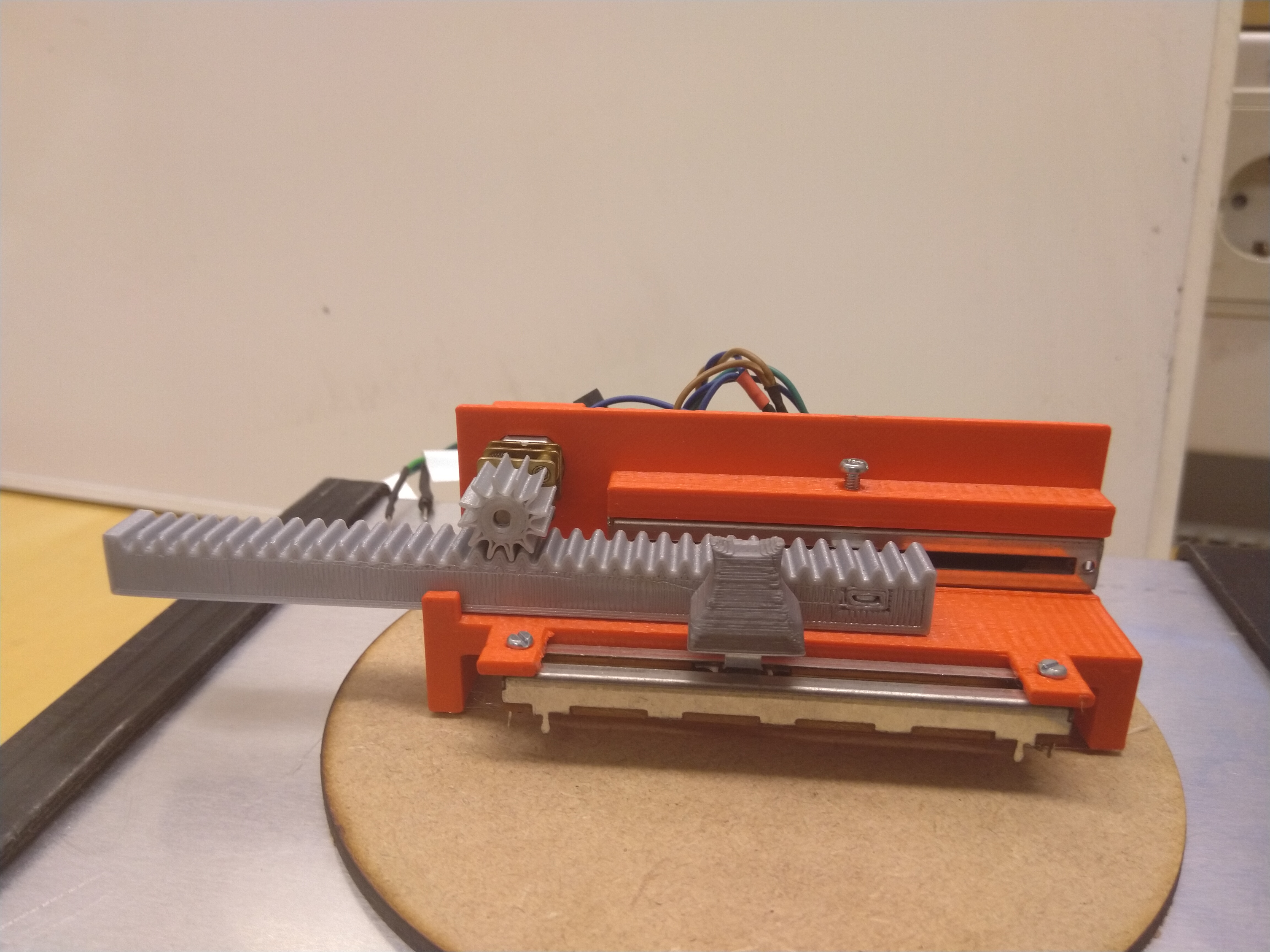
With these instructions, some parts, and a 3D-printer, a 1:1 copy of the actuator can be made.
1. Finding the parts
Parts needed for the actuator are listed in chapter 3. Parts list. There are also links to examples sold in Finland. The same parts can be also found elsewhere, maybe a bit cheaper but with longer delivery times.
2. Printing the parts
The actuator has 3 necessary parts (frame, gear, and rack) and 2 optional parts (potentiometer knob, wire holder) that should be 3D-printed. All the parts can be found as .stl-files, which can be imported into 3D-printing software like Ultimaker Cura for further processing. Rack and pinion gear are simple shaped objects, that are easy to print. The frame as a rather complex shape needs to be printed with supports. With examples made for the course exercises, it was printed H-bridge holder downwards.
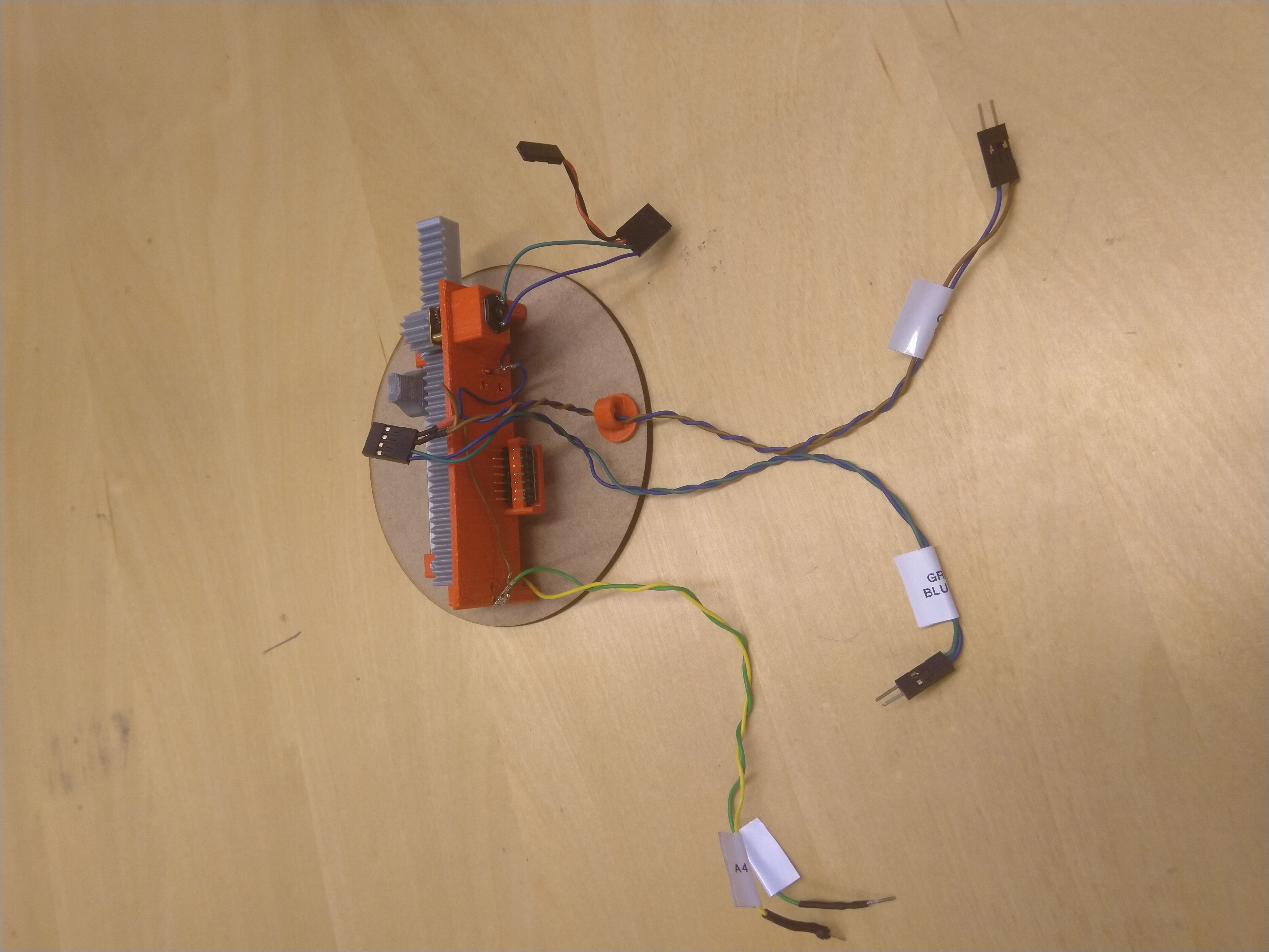
3. Wiring harness
For the wiring, you need thin electrical wires and connectors. Different colored wires are recommended. The wiring can be divided into 3 different parts. For the best result, rigid connections must be done. In this project, standard 0.1" connectors familiar from Arduino boards are used.
- Current for potentiometers and H-bridge control.
-Start with 4 pin female connector.
-Attach two 20cm wires with 2 pin male connectors (from 4 pin connector to Arduino).
-Attach two 20cm wires with 3 pin male connectors (leave the center pin of the connector empty, as this comes to Arduino GND and 3,3V).
-In to the GND and 3,3V wires, add two 10cm wires to each with a "t-tap"-joint. Add a bare metal female connector to each one (these will be soldered to the potentiometers). - Feedback from potentiometers.
-Attach two 20cm wires to 2 pin male connectors (to Arduino). Attach the bare metal female connectors to other ends (to potentiometers). - Battery to H-bridge and motor control.
-Start with the 4 pin female connector.
-Attach two 10cm wires with connector for 9V battery or other power sources (2 pin female connector if you use battery connector from the lab kit).
-Attach two 10cm wires with stripped ends (for DC-motor).

Wiring parts from left to right: part 2, part 1, part 3
4. Assembly
- Press the first potentiometer into the frame and secure it with an 8mm M3 screw.
- Press the DC-motor into its place. The fitment should be so tight that the motor won't fall off.
- Attach the rack to the potentiometer by pressing. Depending on the printing parameters, some material may need to be removed from the slot in the rack.
- Attach the second potentiometer to the frame with 6mm M2,5 screws. Attach the knob to the potentiometer.
- Push the gear into the motor shaft. Again the fitment must be tight enough to prevent gear slipping.
- Slide the H-bridge into its slot. Be careful to ensure no damage is done to any of the parts.
- Solder the wiring harness to the potentiometers and DC-motor.
- Connect the actuator to the Arduino and check that it works.
