CHEM-E4175 - Fundamental Electrochemistry, 09.01.2019-18.02.2019
This course space end date is set to 18.02.2019 Search Courses: CHEM-E4175
Kirja
4. Electrochemical cells
4.1. Electrochemical cell conventions
A number of conventions are needed in the presentation of electrochemical cells. First, reduction will always take place at the cathode and oxidation at the anode. Electrodes are called cathodes and anodes in both galvanic and electrolysis cells. Chapter 1 states that it is impossible to measure the potential of any particular electrode: one always measures or controls the potential difference between two electrodes, i.e. the cell potential. It is not appropriate to call electrodes cathodes and anodes in electrochemical analysis. The reaction of interest takes place at the working electrode and the other electrode in the system is called the counter electrode. The purpose of the counter electrode is to maintain the electroneutrality of the solution: the reaction occurring at the counter electrode is opposite the one taking place at the working electrode (oxidation or reduction). The potential difference between these two electrodes, the cell potential, is easily measurable. As seen in the simplified scheme in Figure 4.1, the cell potential is the sum of different potential differences. In Figure 4.1, the cell potential is composed of the electrode potentials due to a potential change as a result of an electric double layer (Chapter 5) close to the electrode surface. We will show later how this potential difference controls the faradic reactions taking place at the electrode. In addition, an ohmic iR drop affects the cell potential when current flows in the system. This iR drop is caused by the limited conductivity or the resistivity of the electrolyte solution, which is a function of the ionic strength, the dielectric constant of the solvent, and the distance between the electrodes. Only if the iR drop (or loss) can be assumed to be negligible can the measured cell potential be taken as the potential difference between the electrodes. Furthermore, different liquid junctions caused by the structure of the cell (Chapter 4.4.) can complicate the situation.
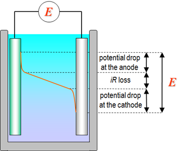
Figure 4.1. Potential profile in an electrochemical cell.
In electrochemical potentiometric methods, the aim is to accurately measure the potential of the working electrode. In electrochemical amperometric methods, the aim is to accurately control the potential of the working electrode and to measure the current. Because the experimental quantity to measure or control is the cell potential, it is clear that in order to accurately know the potential of working electrode, the potential of counter electrode needs to be constant and the iR drop contribution has to be negligible or known.
A counter electrode with a constant potential requires a half-cell where the exchange current density of the half-reaction is very large (Chapter 1.3.4) and the electrode is ideally unpolarizable. The solution components of the half-reaction need to be present in high concentration so the current passing through the electrode will not change the concentrations. An electrode like this is called a reference electrode. When current is flowing in the electrochemical cell, as is usually the case in electrochemical analysis, the use of two electrodes is not sufficient to accurately control the potential of working electrode. In these cases, so called three-electrode set-up is used (Chapter 4.7). 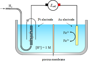
Figure 4.2. Galvanic cell with a standard hydrogen electrode as an anode and a gold electrode in Fe3+/Fe2+-solution as a cathode.
An example of a galvanic cell is presented in Figure 4.2. The standard hydrogen electrode is an anode; there is an agreed convention that it is always presented on the left-hand side of the scheme. The standard hydrogen electrode is a platinum black (very fine platinum powder) plated platinum disc. Hydrogen gas (at pressure of 1 bar) is passed over the disc in solution where the H+ ion concentration is 1 M. A gold electrode is immersed in a solution containing Fe3+ and Fe2+ ions. The acidic solution in the anode compartment and Fe3+/Fe2+ solution in the cathode compartment are separated from each other with a porous diaphragm. The purpose of the diaphragm is to prevent the direct mixing of the electrolyte solutions as this can lead to undesired side reactions and/or make the theoretical treatment of the cell difficult. Ions will pass through the diaphragm and hence current flows. The connection between the two solutions can also be achieved by using a salt bridge (Chapter 4.4.1).
A cell diagram shows the parts of a (galvanic) cell in a concise manner. The different phases in the cell are written from left to right. A boundary between two phases is represented with | and a salt bridge (or any other liquid junction with a small junction potential) with ||. The cell diagram for the cell in Figure 4.2 is:
Cu | Pt | H+, H2 || Fe3+, Fe2+ | Au | Cu
The copper phases on both ends are the conductors, which connect the cell to the potentiometer.
The electrochemical reactions that take place in the cell in Figure 4.2 are:
| at the cathode: Fe3++ e– \(\ce{ <=> }\) Fe2+ | (4.1) |
|---|
| at the anode: ½ H2 \(\ce{ <=> }\) H+ + e– | (4.2) |
|---|
Electric current is a property of a closed circuit. In this cell, electrons move from the hydrogen gas oxidising at the platinum anode through the external circuit to the cathode. At the cathode, electrons move back to the solution through the reduction of iron(III). In the solution, the current is carried by charged components, ions.
Combining reactions (4.1) and (4.2), the total cell reaction is:
| ½ H2 + Fe3+ \(\ce{ <=> }\) H+ + Fe2+ | (4.3) |
|---|
When considering electrochemical net cell reactions, it is advisable to keep in mind that the reaction equation represents a virtual reaction. The reaction species are not in direct contact through collisions in the solution, but the half-reactions take place heterogeneously on their corresponding electrodes. The equilibrium depicted by the reaction equation could only be realized if the electrons could move freely in the external circuit. If the cell is in equilibrium, the net current in the cell would be zero and the cell potential would be also zero (equation (1.6), at equilibrium \( \Delta \)G = 0). In practice, the external circuit holds a high-impedance potentiometer (or load if a galvanic cell is used as a source of voltage), which restricts the flow of current in the circuit. The use of a potentiometer in the circuit therefore results in a situation in which very little current flows in the system. This virtual equilibrium is discussed in the next chapters.
| The value of the cell potential in circumstances where no or very little current is flowing in the cell is an important measurable quantity. This quantity has several names: terminal voltage: maximum voltage available from a particular reaction EMF = electromotive force that moves the electrons equilibrium cell voltage: cell is at equilibrium reversible cell voltage: even a small change in the potential will cause current to flow null voltage/rest voltage: no current is flowing in the cell open circuit voltage: because movement of electrons in the external circuit is impeded, the situation is equivalent to the case of an open circuit |
|---|
Let us consider the measurement of the potential of the cell in Figure 4.2. According to an agreement, the potentiometer (voltmeter) is connected to a galvanic cell in such a manner that the potential is defined as the potential of the right-hand side electrode with reference to the left-hand side electrode *:
| Ecell = Eright – Eleft | (4.4) |
|---|
The electrode with reference to which the potential is measured and therefore the value of the potential is defined is the reference electrode. In the cell shown in Figure 4.2, the reference electrode is the standard hydrogen electrode on the left. The other electrode is the working electrode. It would often be useful to know the potential of a half-reaction. The measurement gives the total cell voltage, i.e. the difference between the half-cell potentials. In order to access the potential value for a half-reaction, another agreement is needed to divide the measured potential between the two half-reactions. This agreement and the measurement of standard potentials is presented in Chapter 4.3.
* In practice the voltmeter measures the galvani potential difference between the poles of the cell (Chapter 1.3.3). The poles of galvanic cells therefore need to be made of the same material.