CHEM-E4175 - Fundamental Electrochemistry, 09.01.2019-18.02.2019
This course space end date is set to 18.02.2019 Search Courses: CHEM-E4175
Kirja
8. Impedance technique
8.4. Adsorption
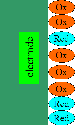
Many electrochemical processes include an
adsorption step, which may even limit the rate of charge transfer mechanism. Let
us look at a simplified theoretical situation, in which a redox pair immobilized
on an electrode determines the rate of reaction alone, as illustrated in Figure 8.13.
The current density is
| \( \displaystyle i=-nF\frac{d\Gamma_{\text{R}}}{dt}=nF\frac{d\Gamma_{\text{O}}}{dt} \) | (8.34) |
|---|
\( \Gamma_{\text{R}} \) and \( \Gamma_{\text{O}} \) are surface concentrations of reduced and
oxidized species, mol cm-2. Additionally, it is assumed
that the molecules do not dissolve from the surface, but at all times it holds that \( \Gamma_{\text{R}}(t)+\Gamma_{\text{O}}(t)=\Gamma_{\text{max}} \). A characteristic feature of the system is that when the electrode is
set to an arbitrary potential, the surface concentrations become such that the Nernst
equation always holds, i.e. every steady state is an equilibrium state at the
same time.
| \( \displaystyle\left(\frac{\Gamma_{\text{O}}}{\Gamma_{\text{R}}}\right)_{eq}=\theta_{eq}=\text{exp}\left[\frac{nF}{RT}(E_{eq}-E^0)\right] \) | (8.35) |
|---|
Analogously to Equation (8.18), a linearized current-voltage equation is expressed as
| \( \displaystyle\overline{\eta}(s)=\frac{RT}{nF}\left(\frac{\overline{i}(s)}{i_0}-\frac{\overline{\Gamma}_{\text{R}}(s)}{{\Gamma}_{\text{R},eq}}+\frac{\overline{\Gamma}_{\text{O}}(s)}{{\Gamma}_{\text{O},eq}}\right) \) | (8.36) |
|---|
The surface concentrations in the Laplace domain can be obtained directly from Equation (8.34):
| \( \displaystyle\overline{i}(s)=-nF(s\overline{\Gamma}_{\text{R}}(s)-\Gamma_{\text{R}, eq})=nF(s\overline{\Gamma}_{\text{O}}(s)-\Gamma_{\text{O}, eq}) \) |
(8.37) |
| \( \displaystyle
\frac{\overline{\Gamma}_{\text{R}}(s)}{{\Gamma}_{\text{R}},eq}=\frac{1}{s}-\frac{\overline{i}(s)}{nF\Gamma_{\text{R},eq}}\frac{1}{s}
\) ; \(
\displaystyle\frac{\overline{\Gamma}_{\text{O}}(s)}{{\Gamma}_{\text{O},eq}}=\frac{1}{s}+\frac{\overline{i}(s)}{nF\Gamma_{\text{O},eq}}\frac{1}{s}
\) |
(8.38) |
|---|
Substitution into Equation (8.36) gives
| \( \displaystyle Z=\frac{RT}{nFAi_0}+\frac{RT}{n^2F^2A}\left(\frac{1}{\Gamma_{\text{R},eq}}+\frac{1}{\Gamma_{\text{O},eq}}\right)\frac{1}{j\omega}=R_{ct}+\frac{1}{j\omega C} \) |
(8.39) |
|---|
The immobilized layer is modeled in impedance measurements as a combination of a resistor and capacitor in series, which is displayed as a semicircle on the admittance plot. The surface concentrations at equilibrium, \( \Gamma \)R,eq and \( \Gamma \)O,eq, can be determined using the Nernst equation and mass balance:
| \( \displaystyle\Gamma_{\text{O,}eq}=\Gamma_{\text{max}}\frac{\theta}{1+\theta} \) ; \( \Gamma_{\text{R,}eq}=\Gamma_{\text{max}}\frac{1}{1+\theta} \) |
(8.40) |
|---|
Now the quantity i0 can hardly be called exchange current density because it depends on the potential:
| \( \displaystyle i_0=nFk^0(\Gamma_{\text{R,}eq})^{1-\alpha}(\Gamma_{\text{O,}eq})^\alpha=nFAk^0\Gamma_{\text{max}}\frac{\theta^\alpha}{1+\theta} \) | (8.41) |
|---|
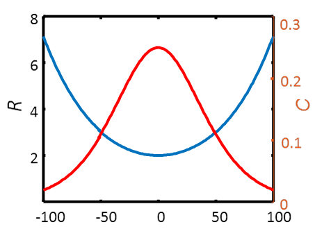
The unit for rate constant k0 is in this case s-1. The charge transfer resistance and capacitance are expressed as
| \( \displaystyle R_{ct}=\frac{RT}{n^2F^2A\Gamma_{\text{max}}k^0}\frac{\theta^\alpha}{1+\theta} \) |
(8.42) |
| \( \displaystyle\frac{1}{C}=\frac{RT}{n^2F^2A\Gamma_{\text{max}}}\frac{(1+\theta)^2}{\theta} \) |
(8.43) |
|---|
These
quantities as a function of potential without the constants are shown in Figure 8.14.
It is worth noting the high value of capacitance. A typical value for \( \Gamma \)max is 10-9 mol cm-2. If we substitute this value into the equation, the maximum capacitance becomes approximately 1 mF cm-2. The surface area of a porous material is high, and it is therefore possible to construct superconductors using immobilized redox species. The charge transfer resistance is also higher than usual. Assuming values \( \Gamma \)max = 10-9 mol cm-2 and k0 = 1 s-1, the order of magnitude of the maximum value of Rct will become 100 \( \Omega \) cm2.
Let us take a look at a model, which is a bit more realistic. In this model, a metal cation M+z is first adsorbed on the surface of the electrode and then reduced to a metal. The current density is
| \( \displaystyle\frac{i}{nF}=-k_c\Gamma_{\text{M}}=-k^0e^{-\alpha f(E-E^{0'})}\Gamma_{\text{M}} \) | (8.44) |
|---|
where n = z,
and the subscript ’c’ of kc denotes cathode process
and thus current is negative. The surface concentration of the cation \( \Gamma \)M can be expressed in terms of maximum surface
concentration and surface coverage \( \varphi \)*, \( \Gamma \)M = \( \Gamma \)max
\( \varphi \). The mass balance of the adsorbed cation is
| \( \displaystyle\frac{\partial\varphi}{\partial t}=\frac{i}{nF\Gamma_{\text{max}}}+k_ac_{\text{M}}^s(1-\varphi)-k_d\varphi=\frac{i}{nF\Gamma_{\text{max}}}+k_ac_{\text{M}}^s-(k_ac_{\text{M}}^s+k_d)\varphi \) | (8.45) |
|---|
where ka
and kd are adsorption and
desorption rate constants. It is therefore assumed that the adsorption is of a Langmuir
type. Let us simplify the expression by ignoring concentration polarization and
keeping solution concentration, \( c_{\text{M}}^s=c_0 \), constant, which means
that adsorption is the rate-limiting step. At a steady state, \( \partial\varphi/\partial t=0 \), and therefore
| \( \displaystyle\varphi_{ss}=\frac{i_{ss}/nF\Gamma_{\text{max}}+k_ac_0}{k_ac_0+k_d} \) | (8.46) |
|---|
The subscript ’ss’ denotes steady state. Linearizing Equation (8.44) and
transforming it to the Laplace domain gives
| \( \displaystyle\frac{\Delta\overline{i}(s)}{nF}=-k_c\Gamma_{\text{max}}(\Delta\overline\varphi(s)-\alpha f\varphi_{ss}\Delta\overline{E}(s)) \) | (8.47) |
|---|
Equation (8.45) is linear to begin with, so after
Laplace transformation we have
| \( \displaystyle s\Delta\overline{\varphi}(s)=\frac{\Delta\overline{i}(s)}{nF\Gamma_{\text{max}}}+\frac{k_ac_0}{s}-(k_ac_0+k_d)\Delta\overline\varphi(s) \) |
(8.48) |
| \( \displaystyle \Rightarrow
\Delta\overline{\varphi}(s)=\frac{\Delta\overline{i}(s)}{nF\Gamma_{\text{max}}(s+k_ac_0+k_d)}+\frac{k_ac_0}{s(s+k_ac_0+k_d)}
\) |
(8.49) |
|---|
| \( \displaystyle\frac{1}{nFA\Gamma_{\text{max}}}=-k_c\left(\frac{1}{nFA\Gamma_{\text{max}}(j\omega+k_ac_0+k_d)}-\frac{\alpha nF}{RT}\varphi_{ss}Z\right) \) | (8.50) |
|---|
Simplifying the expression gives
| \( \displaystyle Z=\frac{RT}{\alpha n^2F^2A\Gamma_{\text{max}}\varphi_{ss}}\left[\frac{1}{k_c}+\frac{1}{j\omega+k_ac_0+k_d}\right] \) | (8.51) |
|---|
The first term of Equation (8.51) is not
dependent on frequency, and thus it represents the charge transfer resistance. The
second term is a combination of two elements, and after giving it some thought,
it becomes evident that the term represents the parallel combination of a capacitor and a resistor. The equivalence circuit becomes complete when the double layer
capacitance, which is always present, is added in parallel with this faradaic
impedance, and we obtain the equivalent circuit and impedance plot displayed in
Figure 8.15.
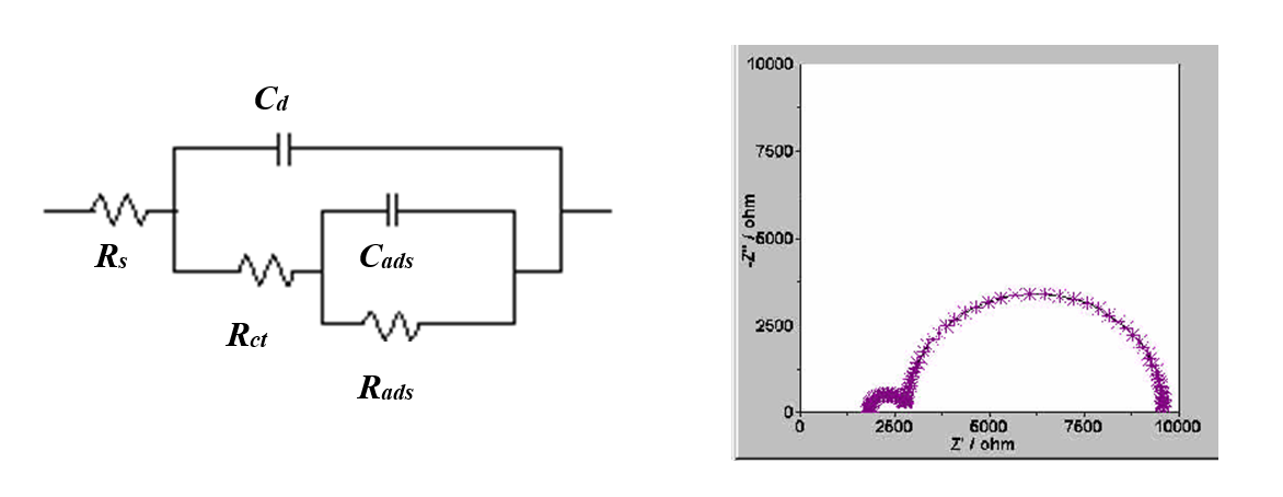
Figure 8.15. Equivalent circuit and impedance plot for an electrode reaction with an adsorption step.
Substituting jss into Equation (8.51), which we obtain using Equations (8.44) and (8.46):
| \( \displaystyle\varphi_{ss}=\frac{k_ac_0}{k_ac_0+k_d+k_c} \) | (8.51) |
|---|
Let us find the final expressions for Rct, Rads and Cads:
| \( \displaystyle R_{ct}=\frac{RT}{\alpha n^2F^2A\Gamma_{\text{max}}k_ac_0}\left(1+\frac{k_ac_0+k_d}{k_c}\right) \) |
(8.52) |
|---|---|
| \( \displaystyle R_{ads}=\frac{RT}{\alpha n^2F^2A\Gamma_{\text{max}}k_ac_0}\left(1+\frac{k_c}{k_ac_0+k_d}\right) \) |
(8.53) |
| \( \displaystyle C_{ads}=\frac{\alpha n^2F^2A\Gamma_{\text{max}}k_ac_0}{RT(k_ac_0+k_d+k_c)} \) |
(8.54) |
Values for physical parameters can be
determined as follows:
| \( \displaystyle\frac{R_{ct}}{R_{ads}}=\frac{k_ac_0+k_d}{k_c} \) |
(8.55) |
| \( \displaystyle R_{ads}C_{ads}=\frac{1}{k_ac_0+k_d} \) |
(8.56) |
| \( \displaystyle R_{ct}C_{ads}=1/k_c \) | (8.57) |
|---|
The impedance method therefore gives the value of the electrochemical rate constant explicitly, but finding the values of adsorption and desorption constants requires measurements at varying solution concentrations c0.
We have now shown that adsorption is observed as capacitance in impedance measurements. The derivation of impedance for more complicated mechanisms is, in principle, as simple as this; the only difference is that the mathematical treatment required is more extensive. The study of more complicated mechanisms is outside of the scope of this book. However, it is worth noting that even the previous example would be hopelessly difficult to study using other transient methods, and an analytical solution to the problem would not be possible.
* The symbol for surface coverage is usually \( \theta \), but we have already reserved it for the quantity exp[(nF)/(RT)(E - E0’)].