CHEM-E4175 - Fundamental Electrochemistry, 09.01.2019-18.02.2019
This course space end date is set to 18.02.2019 Search Courses: CHEM-E4175
Kirja
4. Electrochemical cells
4.7. Three-electrode set-up
The two-electrode set-up presented so far in this chapter is not sufficient to accurately control the potential of the working electrode in an electrochemical cell. If the reference electrode is also working as a counter electrode, the flow of current through the electrode can cause momentary changes in concentrations, and the potential of the electrode does not stay in the expected constant value. This is a problem in large-scale electrolysis or in the use of fast voltammetric analysis methods in organic solvents in particular. When current is flowing, the possible effect of the ohmic drop has to be taken into account and minimized. In organic solvents, this can be a particularly important issue.
These problems are circumvented with the three-electrode set-up, which is the basis of modern electrochemical measurements. A three-electrode set-up is presented in Figure 4.5. The idea is as follows: external voltage Vin is applied between the reference (RE) and the working electrode (WE), and an operational amplifier ensures that no electric current flows between these two electrodes. Electric current is passed from the counter electrode (CE) to the working electrode in a way that the external voltage required is achieved This is again enabled by an operational amplifier. As there is virtually no current flowing through the reference electrode (and it is non-polarizable), its potential is constant. The change in Vin is therefore the same as the change in the potential of the working electrode. The development of electronics has raised electrochemical analysis methods to a new level since the discovery of polarography.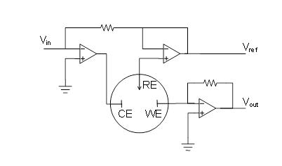
Figure 4.5. Potentiostatic three-electrode set-up. The current flowing through the cell is obtained from Vout.
In principle, the counter electrode in three-electrode set-up can be made of any conductive material as long as its electrochemical behavior does not affect the function of the working electrode. Typical materials for counter electrodes are platinum or graphite. The counter electrode should be placed in the cell in such a way that the products from the reaction on it are not be able to reach the working electrode and affect the reactions taking place there. In practice, this is not a problem due to the slow diffusion of these products, and it is not necessary to place the counter electrode in a separate compartment. The area of the counter electrode needs to be large compared to the area of the working electrode to prevent the reactions at the counter electrode from being the current-determining reactions in the cell.
The reference electrode has to be placed close to the working electrode in order to minimize ohmic losses. This can be achieved by using a Luggin capillary (Figure 4.6.). In this set-up, the reference electrode, for example the Ag/AgCl electrode previously introduced, is placed in a glass capillary that has a narrow tip (Luggin capillary). The capillary is usually filled with the solution being studied. The reference electrode is placed next to the working electrode via this narrow tip. As the distance between the tip and the working electrode is very small, the ohmic drop between the reference electrode and the working electrode is small. The ideal location of a Luggin capillary at the working electrode needs to be experimentally investigated, and it should be kept constant in the measurements. The Luggin capillary should be very close to the working electrode but not touch it.
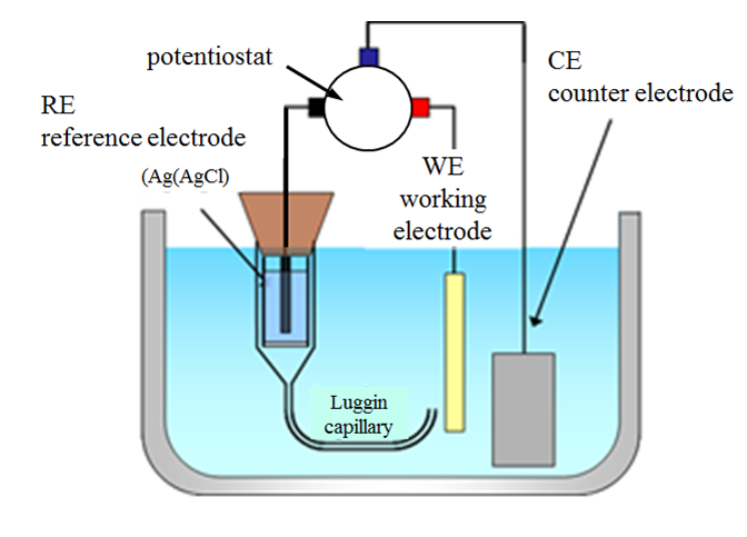
Figure 4.6 Three-electrode set-up.
The device used to carry out electrochemical measurements is called a potentiostat. A potentiostat is based on the circuit presented in Figure 4.5. A potentiostat can be switched to the galvanostatic mode, where the current flowing through the working electrode is controlled and the potential of the working electrode with reference to the reference electrode is measured. Potentiostats offer means to tackle ohmic losses, usually either the ohmic losses in the cell can be measured or it is possible to compensate for them electronically by means of a positive feedback loop.