NC Machining
Haas TL1
In the turning process a workpiece is spinning and a tool is used to take material away until the desired shape has been machined.
Maximum diameter. 250mm
Maximum length: 500
Picture 1: Piece being turned on the lathe
THE FILE
In the start of the project the designer and workshop master will have discussion about the part to be made. Technical drawing and a render of the part should be presented. The workshop master will comment if iteration of the part is needed for machining. A Outline drawing is then imported into a cam program and the cutting paths are created based on the model and consensus between the designer and the machinist. It is important to include measuments and mark out the most important measures on the technical drawing.
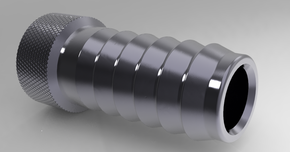
Image2: rendering of the desired part
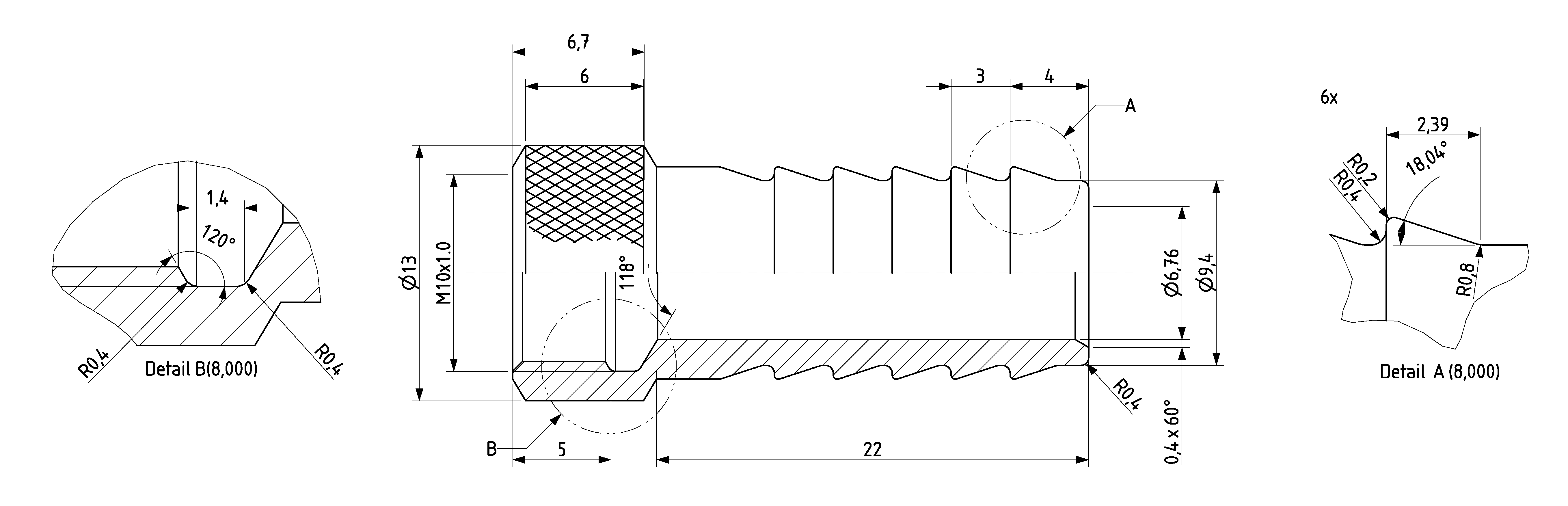
Image3: Technical drawing of the part
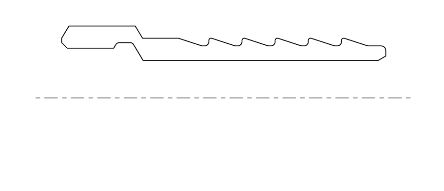
Image4: Drawing used for the machining
In the outline drawing, the thread and the knurling are not modelled.
For outer threads model the thread as nominal outer diameter.
For inner threads model the thread as nominal inner diameter.
Runout for thread is tool dependant, please ask the workshop master for spesifications for modeling runout.
As per example in above images.
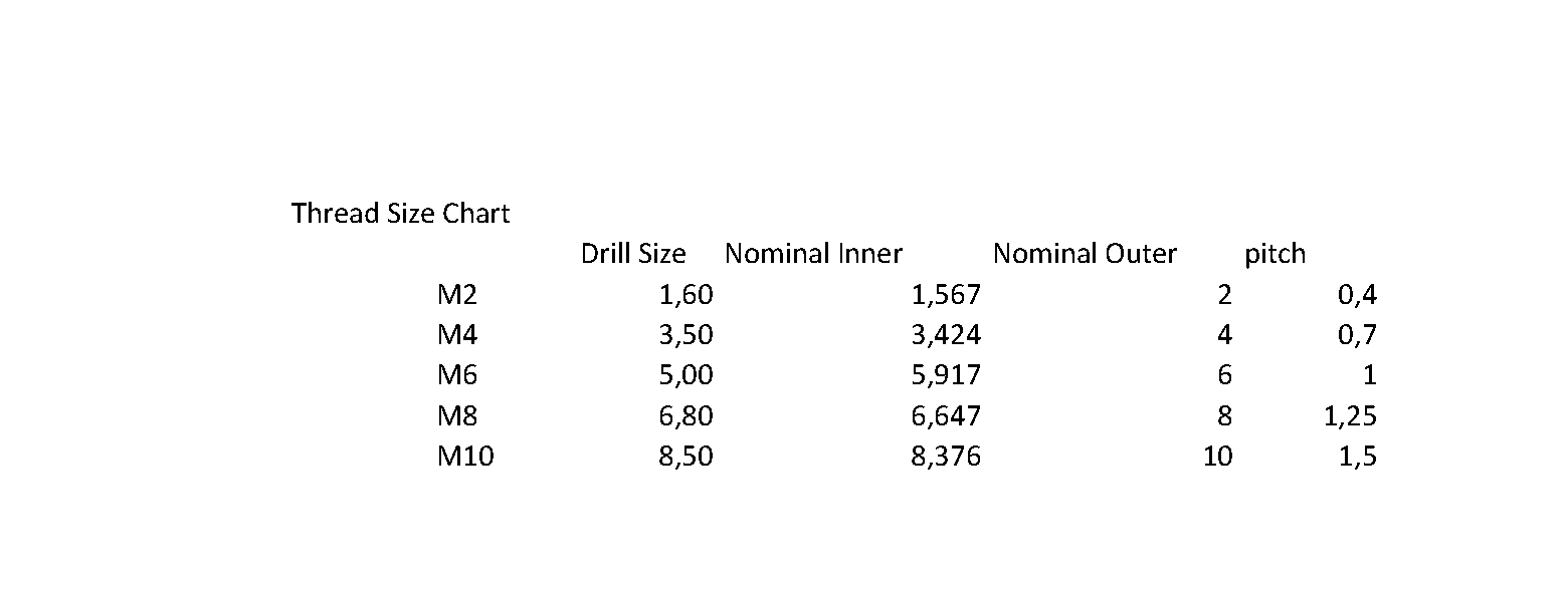
Image5: Metric thread table