KON-C3003 - Mekatroniikan harjoitustyö, Luento-opetus, 10.1.2023-13.4.2023
This course space end date is set to 13.04.2023 Search Courses: KON-C3003
Servo test bench
Completion requirements
Demonstration and test device for three different size RC-servos
3. Hardware
Under the polycarbonate panels of the device, there is quite a lot of electronics:
- Converts the 230V alternating current to 12V direct current.
- Easy to use terminals with proper labels.
- Non-insulated, needs caution.
- Power cord was taken from an old coffee machine.
- Strain relief as shown below was made by printing a clamp inside the device.

- Drops the voltage to 5V for Arduino.
- Needs a circuit board
Arduino microcontroller
- A regular UNO or similar works fine.
- With enough motors, an Arduino with more pins is needed.
- 16 channels -> 16 separate motors
- Uses I2C to communicate with Arduino
Servo motors
Behaviour of the servos is inspected with a help of different sensors:
- Amplify the signal coming from the load cells.
- Placed in a solderable copper plated circuit board.
- HX711 is quite a common example and has a good library.
- Two strain gauges per load cell.
- Cells need calibration.
- Many different maximum load ratings available.
- For measuring the rotational speed of servos.
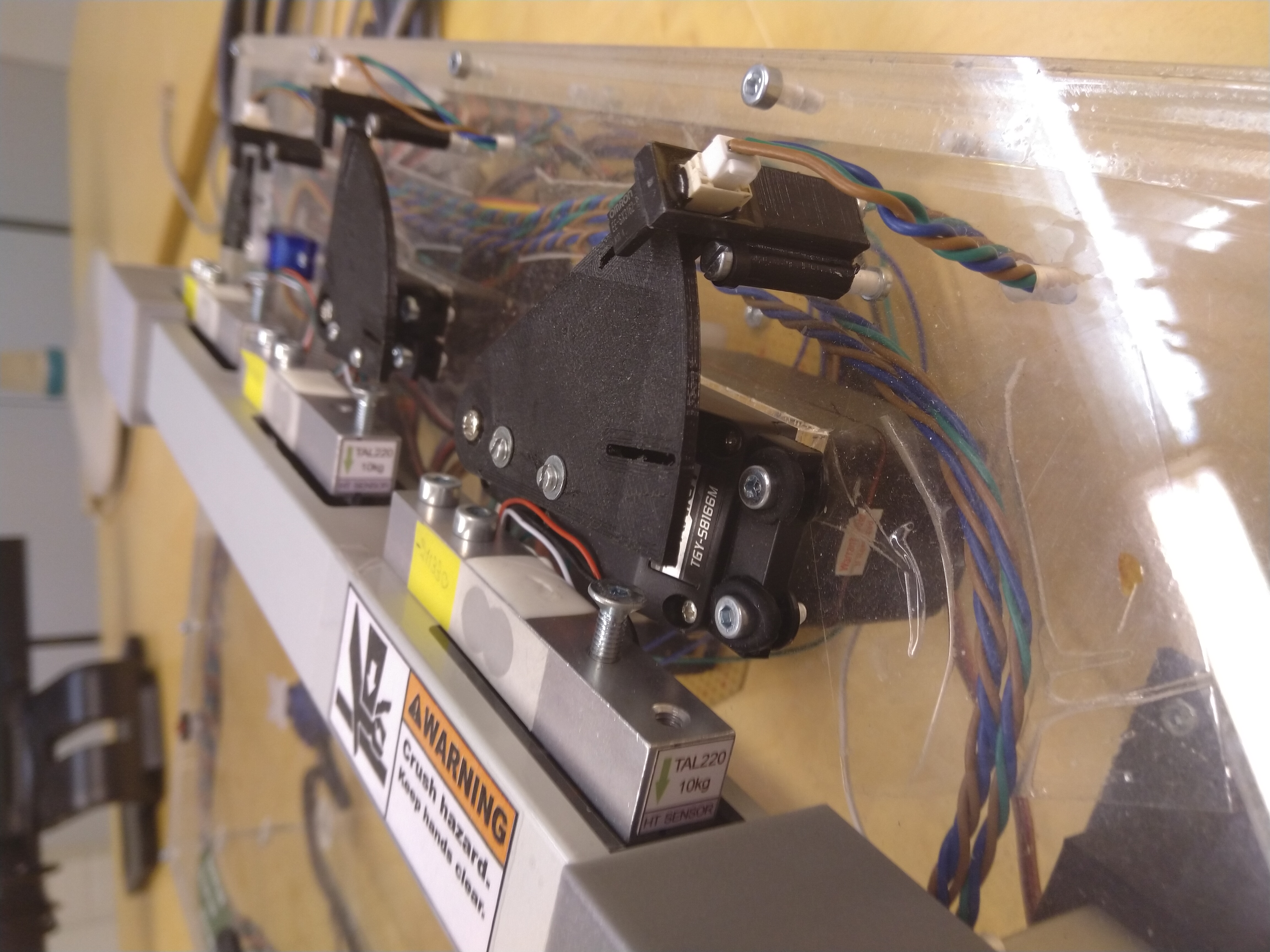
- Plates with holes were printed and attached to servos. Optical switch detects the holes when the servo rotates. The speed is then counted from the time taken to rotate the certain angle between the holes.
- Need to be positioned precisely.

Optical switch and load cell.
To operate all this, a user interface is needed:
- Connected to Arduino via I2C.
- Common model, available both with or without I2C module.
Buttons and toggle switches
